Model
5340A
Theory
of
Operation
A
B
L
L
L
H
H
L
Ha H
SECTION
IV
THEORY
OF
OPERATION
Z
H
H
H
L
4-1.
INTRODUCTION
4
-
2.
This section describes the individual logic elements, overall counter operation, and theory
of
operation for each printed circuit assembly. The overall counter theory
starts
in Paragraph
4
-
103.
The theory for each pc board
starts
in Paragraph
4
-
137.
4
-
3.
LOGIC ELEMENTS
4
-
4.
Two states exist in the binary system,
1
and
0.
HIGH (H) and
LOW
(L)
are used to represent
the levels of
1
and
0.
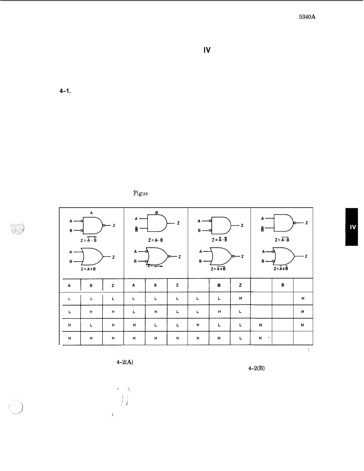
HIGH always represents the more positive level, whether it be positive or
negative logic. Figure
4
-
1
shows four pairs of logic symbols that have the same truth tables and
can be used interchangeably. The same function
is
performed by what appears
to
be two dif
-
ferent logic symbols.
Figue
4
-
1.
Logic Comparison Diagrams
plslz
B
A€)-z
B
Z=
A.B
B+L!
Z=
A+B
I
C
--
Z=
A.B
Z=A+B
A
B
z
~
D
"DZ
B
Z=
AT0
z-
3it
B
4
-
5.
GATES.
Figure
4-2(A)
represents a basic
AND
gate. The AND gate output
is
HIGH if all
inputs are HIGH. An AND gate may have two or more inputs. Figure
4-2(B)
represents
a
basic
OR
gate. The
OR
gate output
is
HIGH if one or more of
its
inputs
is
HIGH.
An
OR
gate may
have two or more inputs.
/
,
1;
!I
1
4
-
1