Model
5340A
Theory of Operation
4
-
124. Harmonic Determination Circuitry
4
-
125.
When sampler
No.
2
produces an
FIF~
output, the bandpass filter and preamp
A2A4
provide a
6
MHz bandpass. Limiter amplifier
-
mixer
A14
receives FIF2, and the
20
MHz
reference from
A15.
When
20
MHz
is
mixed with
FIF2,
a
difference frequency that
is
equal
to
N
20
kHz
is
produced. The value of
N
is
determined
in
the counter circuits and used
as
a
gate
extension factor.
4
-
126.
SAMPLING
THEORY
4
-
127.
Sampling techniques are used for measuring frequencies that are too high to count with
direct counting circuits. This method provides an output signal whose frequency
is
a fraction of
the input frequency and low enough to count directly. The
534QA
uses
a
20
MHz phase lock loop.
However for simplicity,
a
dc phase lock loop will be described followed by an explanation of the
type of phase lock techniques used in the
5340A.
4
-
128. A
sampler looks
at
the input signal for
a
brief interval of time and charges a capacitor
to the instantaneous voltage of the signal. For each sample event, the capacitor charges to the
instantaneous voltage of the input waveform. Figure
4
-
46
shows one method of sampling using
a
diode
as
a switch.
Figure
4
-
46.
Sampling Diode Switch
==+-
INPUT
SIGNAL
4
-
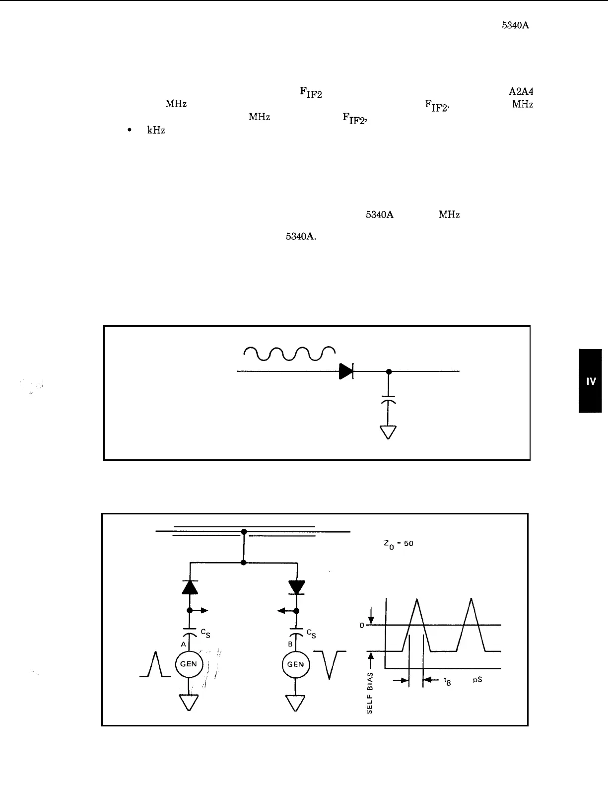
129.
To
minimize sampling pulses on the input signal,
a
balanced sampler
is
used as shown in
Figure
4
-
47.
The outputs
of
the balanced sampler connect to an amplifier for summing.
Figure
4
-
47.
Balanced Sampler
OUTPUT TRANSMISSION
LINE
zo=
50
INPUT
OUTPUT
TO
AMPL
v
*
+t
t7
t8
=
40
pS
I+
4
-
35