Model 5340A
Theory of Operation
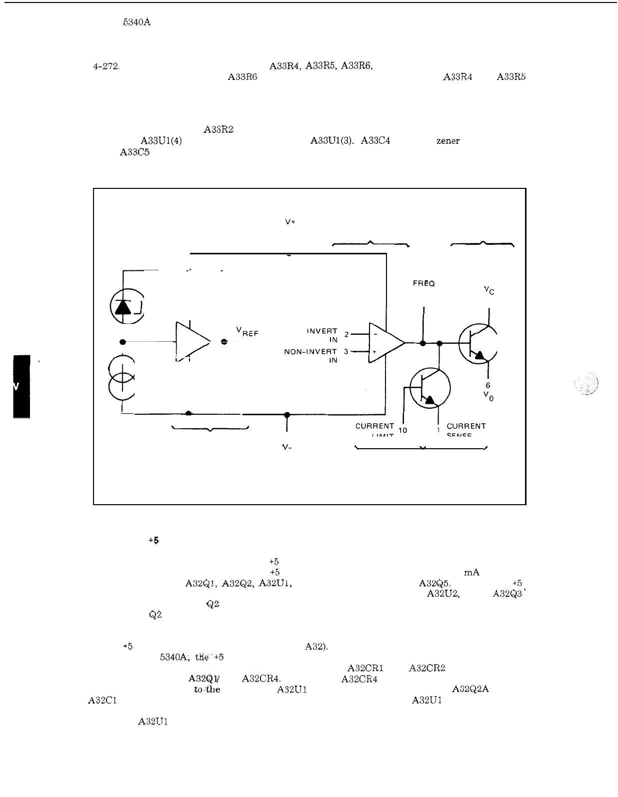
4-272. The current limiter consists of A33R4, A33R5, A33R6, and the current limiter transistor
in the IC (see Figure 4
-
52). A33R6 determines the current limit point and A33R4 and A33R5
determine the foldback current limit operation. When the drop across R6 is sufficient to forward
bias the current limit transistor (Figure 4
-
52), the current limit transistor draws base current
away from the series pass transistor thereby reducing the output voltage and limiting the current.
The foldback current limiting provides
a
further reduction in current to prevent excessive power
dissipation in the IC.
A33R2 provides temperature compensation and supplies the reference
voltage
at
A33U1(4) to the noninverted input
at
A33U1(3).
A33C4 bypasses Zener diode noise on
Vref.
A33C5 provides frequency compensation to prevent high frequency oscillations.
Figure 4
-
52. Equivalent Regulator Circuit
V+ ERROR
SERIES PASS
a
AMPL
TRANSISTOR
I
-
a
-
FREO
COMP VC
9
7
4b
a
"REF
-
4
CURRENT
SOURCE
a
-
VOLTAGE
5
REF AMPL V-
\
./
/
CURRENT
LIMITER
4
-
273. A32
+5
Volt
Regulator
Assembly, 05340
-
60023
4
-
274.
A32 (Figure 8
-
34) contains two
+5
volt regulators, one for the RF circuits and the other
for the digital circuits (+5
DG).
The RF +5 volt regulator supplies approximately
32
mA and con
-
sists
of
preregulator A32Q1, A32Q2, A32U1, and series pass transistor A32Q5. The digital
+5
volt regulator supplies approximately
3
amperes and consists of regulator A32U2, driver A32Q3
'
and series pass transistor
Q2
which
is
mounted on the rear panel of the instrument. Connections
from A32 to
QZ
are made through the power supply mother board A30 and three wires to the
rear panel.
4
-
275. +5 VOLT RF REGULATOR (PART OF A32).
To prevent drift and instability in the RF
circuits of the
5340A, tKe'+b volt RF regulator in A32 (Figure
8
-
34)
uses a preregulator to
achieve the required regulation and low ripple voltage.
A32CR1 and A32CR2 establish
a
con
-
stant current through A32QV and A32CR4.
Zener diode A32CR4 provides a constant
11
volt out
-
put which is connected to.'the Vc input of A32U1 via
a
darlington transistor pair A32Q2A and
B.
A32C1 filters out noise'generated in the Zener diode. The operation of A32U1
is
similar to that
described for the Time Base Power Supply A33 (see Paragraph 4
-
270). The reference supply
voltage for
A32U1 is derived from the +15 volt supply A29.
4
-
52