Model 5340A
Operation
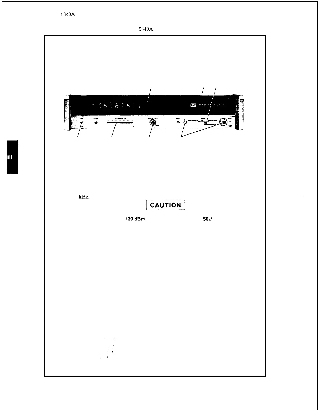
Figure 3
-
5. 5340A Operating Procedures
1.
2.
3.
4.
5.
6.
7.
8.
8
15
2
3.7
6
4
On Rear Panel set INT
-
EXT switch to INT position.
Set LINE switch to on (up) position.
Set RESOLUTION
Hz
to desired resolution. Recommended starting setting
is
1
kHz.
DO NOT EXCEED
t30
dBm
(1
WATT) INPUT AT THE
50Q
N CONNECTOR.
DAMAGE TO THE INTERNAL SAMPLERS MAY OCCUR. PLEASE READ
PARAGRAPH
3
-
21
FOR
DETAILS
OF
ACCEPTABLE INPUT LEVELS.
Connect input signal to appropriate input connector according to input fre
-
quency and impedance requirements.
Set
RANGE
switch
to
correspond with input connector being used.
Adjust SAMPLE RATE control for desired interval between measurements.
Adjust RESOLUTION
Hz
switch for desired number of significant digits.
Display
is
in units shown with correct decimal point and significant digits.
3
-
8