Model 5340A
Operation
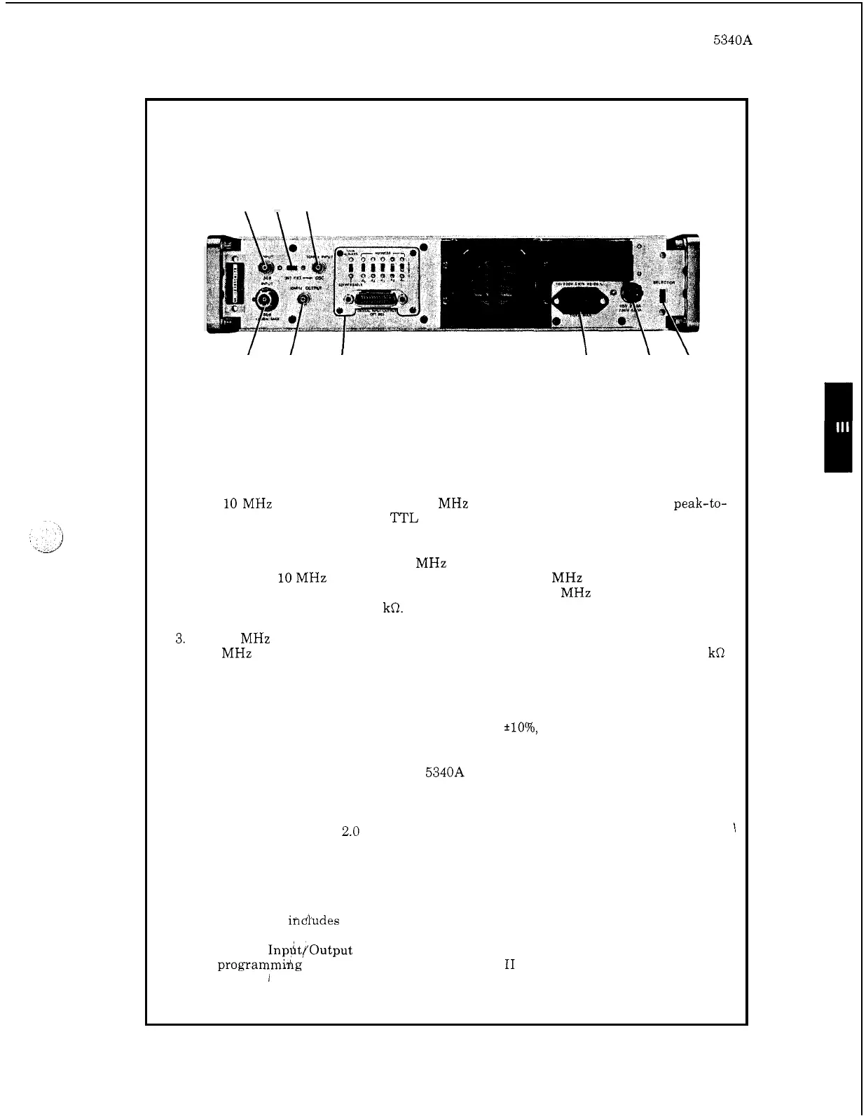
Figure 3
-
4. Rear Panel Controls and Connectors
1.
2.
3.
4.
5.
6.
7.
8.
9.
823
7
1
9
4
6
5
10
MHz
OUTPUT. Supplies a 10
MHz
square wave output
at
2.4
volts peak-to-
peak or greater. Output
is
TTL compatible.
INT
-
EXT OSC switch.
Selects time base source. When set to INT, the counter
operates from its internal
10
MHz
oscillator. When set
to
EXT,
it
allows an
external
10
MHz
sine wave or square wave at the
10
MHz
INPUT jack to operate
the counter. External oscillator requirements are
10
MHz
at
approximately 1.5
volts peak
-
to
-
peak into
1
kR.
10
MHz
INPUT jack.
Accepts external time base signal. Requirements are a
10
MHz
sine wave or square wave
at
approximately 1.5 volts peak
-
to
-
peak
(1
kR
impedance). The INT
-
EXT switch must be set to EXT to accept the external
OSC input.
AC Input Connector.
Ac
power
receptacle. IEC
type
with offset pin connected
to the chassis. Accepts
115
volts or 230 votls
*lo%,
48 to
68
Hz.
Maximum power
draw
is
100
volt amperes.
SELECTOR switch. Allows the
5340A to operate off of 115 volts or 230 volts ac.
Use a narrow bladed screwdriver and slide the switch to show the desired oper
-
ating voltage.
FUSE.
Requires
a
2.0
amp normal blow fuse for 115
-
volt operation or
a
1.0
amp
normal blow fuse for 230
-
volt operation.
Input Option
002
N
connector. Same
as
front panel
N
connector, see Figure 3
-
3.
BNC input connector Option
002.
Similar to front panel BNC input except that
this optiod
ihdhdes a 50
-
ohm termination on the front panel BNC connector.
Digital
InpdtfOutput Option 011.
programmihg and digital output. See Section I1 for details
of
operation.
Connector and address switches for remote
1
3
-
7