Model 5340A
Maintenance and Service
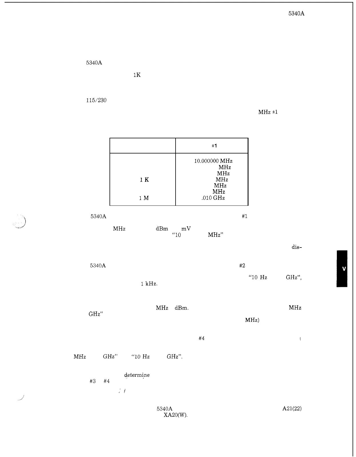
Resolution
1
10
100
1K
10
K
100
K
1M
5
-
24.
OVERALL TROUBLESHOOTING
Display
*1
Count
10.000000
MHz
10.00000
MHz
10.0000
MHz
10.000 MHz
10.00
MHz
10.0
MHz
.010
GHz
5
-
25. Proceed with these tests in the order listed.
a.
Set
5340A controls
as
follows:
RESOLUTION
to
1K
SAMPLE RATE to max ccw
RANGE
to
CHK
OSC
(rear panel) to INT
115/230
V
Selector (rear panel) to match line voltage being used.
LINE (front panel) to
ON
Check that the GATE lamp flashes. The display should be
10.000
MHz
*1
count.
Check that DIRect lamp flashes. Move the RESOLUTION switch through all of its positions
and observe the display.
If the
5340A fails any of these tests, go to Troubleshooting Chart
#1
of Figure 5
-
5.
b.
Connect a 220
MHz signal
at
0 dBm (644 mV p
-
p) to the
1
MR input using
a
50R feedthru
termination. Move RANGE switch to
“10
Hz to 250 MHz” and RESOLUTION to
1
K.
The GATE lamp should flash, the DIRect lamp should be
lit
and the counter should dis-
play the correct frequency for all positions of the RESOLUTION switch.
If the
5340A fails any of the above, go to Troubleshooting Chart #2 of Figure 5
-
5.
Connect the signal to the 50R INPUT, move RANGE switch to
“10
Hz
to
18
GHz”,
RESOLUTION switch to
1
kHz. The GATE lamp should flash, the DIRect lamp should
be lit and the counter should display the correct frequency for all positions of the
RESOLUTION switch.
I
c.
d.
Change input frequency to 280
MHz
0
dBm. Move the RANGE switch to the “250 MHz
to 18 GHz” position. The LOCK lamp should now light, the GATE lamp should continue
to flash and the counter should display the correct frequency (280
MHz) for all positions
of the RESOLUTION switch.
If this test is failed, go to Troubleshooting Chart
#4 (Figure 5
-
5).
i
For each position of the RESOLUTION switch, move the RANGE switch between “250
MHz to
18
GHz” and “10
Hz
to
18
GHz”. The display frequencies should agree within
1
count.
If this test fails,,
+termi,ne which frequency
is
incorrect and use Troubleshooting
Chart
#3
or
#4
(Fi
ure 5
-
5).
e.
4
,I
5
-
26.
A20
N
Checker
Troubleshooting
5
-
27.
Remove A5 05340
-
60003 from 5340A and place A20 on an extender. Short A21(22)
to chassis. Unsolder the wire connected to
XAZO(W).
5
-
17