2
-
1.
INTRODUCTION
2
-
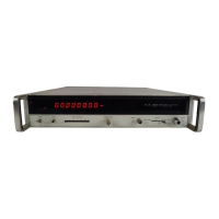
2. This section tells how to set up the 5340A Frequency Counter.
Instructions for unpacking,
inspecting, installing, and remote programming are included.
2
-
3.
UNPACKING AND INSPECTION
2
-
4. If the shipping carton
is
damaged, inspect the counter for visible damage (scratches, dents,
etc.). If the counter
is
damaged, notify the carrier and the nearest Hewlett
-
Packard Sales and
Service Office immediately (offices are listed
at
the back of this manual). Keep the shipping
carton and packing material for the carrier’s inspection. The Hewlett
-
Packard Sales and Service
Office will arrange for repair or replacement of your instrument without waiting for the claim
against the.
camer to be settled.
2
-
5.
INSTALLATION REQUIREMENTS
BEFORE CONNECTING THE INSTRUMENT TO AC
POWER LINES, BE SURE THAT THE LINE SELECTOR
IS
PROPERLY POSITIONED.
.*<
3
.
-
2
-
6.
LINE VOLTAGE REQUIREMENTS. The
5340A
is
equipped with
a
line voltage switch to
select 115
-
volt or 230
-
volt ac operation. Before applying power, the rear panel screwdriver-
operated switch must be set to the correct position (“115” or “230” visible) and the correct fuse
(as
labeled on the rear panel) must be installed. See Figure 3
-
4 for rear panel features.
2
-
7.
between 48
Hz
and 66
Hz.
LINE FREQUENCY REQUIREMENTS.
The
counter will operate
at
line frequencies
2
-
8.
THREE CONDUCTOR POWER
CABLE. To protect the operator, the counter uses a
grounded three
-
conductor detachable power cable. The male connector end
is
a
NEMA type
connector, and the female connector end
is
a
C.E.E. type connector that mates with the 5340A
rear panel power connector.
Connect the power cable to
a
power source receptacle with
a
NEMA grounded third conductor.
If the line power receptacle
is
a
standard two
-
pin type instead
of the NEMA three
-
pin receptacle, use
a
two
-
to
-
three pin adaptor (HP
Part
No. 8120
-
1348) and
connect the green pigtail on the adaptor to ground.
2
-
9.
TEMPERATURE LIMITS. Maximum and minimum allowable operating temperatures ake
listed in Table
1
-
3.
If these limits are exceeded
at
the installation site, auxiliary cooling or
heating should be used to keep the environment within limits.
Model
5340A
Installation and Remote Programming
SECTION
II
INSTALLATION AND REMOTE PROGRAMMING
I
2
-
10.
RACK INSTALLATION. The counter is ready for bench operation
as
shipped from the
factory.
Additional parts necessary for rack mounting are packaged with the instrument.
To
convert the instrument
to
‘rack installation, refer to Figure 6
-
1 for parts identification and pro
-
ceed
as
follows:
,’
i
a. Remove
tilt
stand
MP14
by removing the two outside front feet MPll from the bottom
cover
MP9.
1
The feet are removed by pressing the foot
-
release button and sliding
the foot toward the center
of
the instrument.
b.
Remove the remaining three feet from the bottom cover.
2
-
1

 Loading...