'..
a
low
1w
tw
lWmW
lanW
5mW
1mW
1oojIw
low
3PW
1PW
0.3jIW
a1gw
0.01jIw
Model 5340A
Operation
-
-
-
-
-
-
-
-
-
-
-
-
-
-
3
-
19. Auto
-
Amplitude Discrimination
3
-
20.
This
feature allows the counter to select and measure the signal with the largest amplitude
in the 250
MHz
to
18
GHz
range. This
is
with the provision that the largest signal is 20 dB greater
in amplitude than any other
signal
present. Although
20
dB
is
the guaranteed specification,
typical operation
is
about
10
dB. The auto
-
amplitude discrimination feature
is
useful for dis
-
criminating against harmonics, and spurious signals.
3
-
21. MAXIMUM INPUT SIGNAL POWER
I
CAUTION
]
DO
NOT EXCEED
1
WATT
OF
INPUT POWER AT THE
INTERNAL SAMPLERS MAY OCCUR. PLEASE READ
INPUT LEVELS.
50
-
OHM N CONNECTOR. DAMAGE TO THE
PARAGRAPH
3
-
22
FOR
FULL EXPLANATION OF
3
-
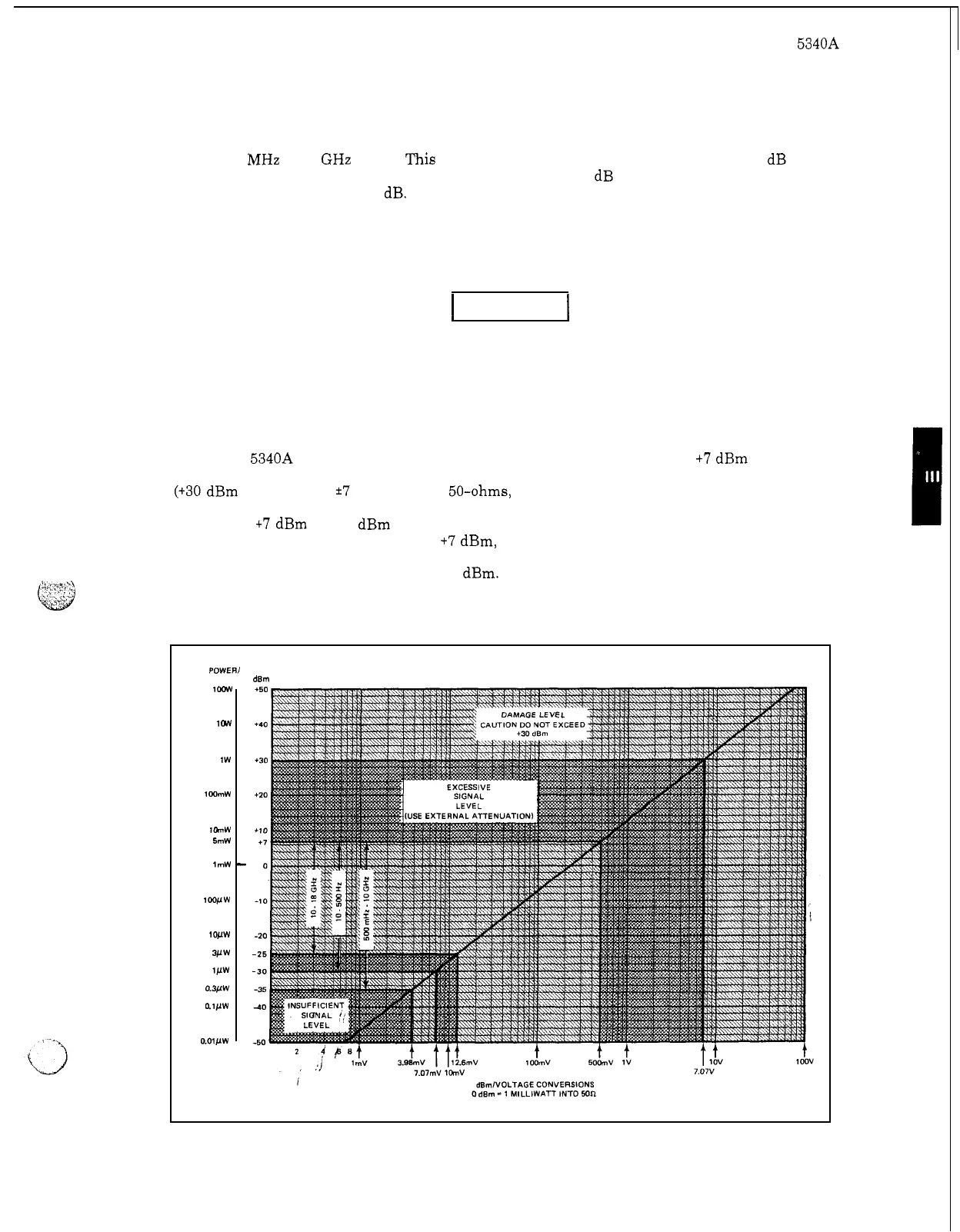
22.
The 5340A will function within specifications for signal inputs up to
+7
dBm (5.012 milli
-
watts or
0.5006
volts into 50
-
ohms). Under no circumstance should the input level exceed 1
-
watt
(+30 dBm
RF
power or
*7
volts dc into 50-ohms, dc power).
If
the input power exceeds 1
-
watt,
damage to the internal samplers may occur and these are quite expensive to replace. Measure
-
ments from
+7
dBm to +30 dBm are not recommended because false harmonic locks and readings
may occur.
When signal levels exceed
+7
dBm, external attenuators should be used. The 1
-
watt
maximum input level
is
the total
RF
and dc power at the input connector. Figure 3
-
2 shows
power levels with conversions
to
volts and dBm.
Figure 3
-
2. DBM to Volts Conversions
POWER1
WATTS
dBm
3
-
3