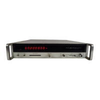
Model
5340A
Operation
SECTION
111
OPERATION
3
-
1.
INTRODUCTION
3
-
2. This section contains operating information including operating characteristics, input cable
considerations, controls and indicators, and operating procedures. Programming instructions
are contained in Section
11.
3
-
3.
OPERATING CHARACTERISTICS
3
-
4. The following paragraphs describe the operating ranges and modes, resolution, sample rate,
AM and FM characteristics, and auto
-
amplitude discrimination.
3
-
5.
Operating Ranges
3
-
6. There are two basic operating ranges available: 10 Hz to 250 MHz and 250 MHz to
18
GHz.
Frequencies in the lower range are measured directly while measurements in the 250 MHz to
18
GHz range are made with an indirect transfer oscillator technique. Provision
is
made to select
three operating ranges, these are:
a.
10
Hz to 250 MHz
at
the
BNC
connector
(1
MR, 25 pF).
b. 250 MHz to 18 GHz
at
the
N
connector (50R).
c.
10 Hz to 18
GHz
at
the
N
connector (50R).
3
-
7. The 10 Hz to 250 MHz range restricts the counter to direct measurements. The 250 MHz to
18
GHz range restricts the counter to the transfer oscillator mode, and the 10 Hz to 18 GHz range
allows both modes of operation to be in effect. Annunciator lights are included to indicate when
the counter is measuring directly (DIR light)
or
indirectly
(LOCK
light).
It
should be noted that
during the
10
Hz to 18 GHz operation, the counter may lock on
a
signal in the 10 Hz to 250 MHz
range in preference to a signal in the transfer oscillator range. Thus, to measure a high frequency
signal
(>250 MHz) containing high levels
of
residual low frequencies,
it
is
necessary to select the
250
MHz
to
18
GHz
range. Otherwise,
the
switch position
is
dictated
by
the impedance require
-
ments and frequency of the input signal.
3
-
8.
Resolution and Blanking
3
-
9. In a frequency counter, resolution can be defined as the value represented by the least,
significant digit
(LSD).
In
the 5340A,
a
maximum resolution of
1
Hz can be selected. Decade
multiples of
1
Hz to
1
MHz are available. For example, with
an
input of 12,345,678 Hz, setting the
RESOLUTION
switch to
1,
the counter displays the 8 in the
LSD.
Selecting 100 on the
RESO
-
LUTION
switch places the 6 in the LSD. If
a
frequency such
as
123,456,789 Hz
is
measured with
1
Hz resolution selected, the counter will overflow
so
that the
1
is
not displayed and the 9 will
appear in the
LSD.
For ,high resolution of measurements which would result in an overflow, two
measurements can be made.' The first measurement
is
made with
a
resolution setting that is
adequate
to
display the mqst significant digits. The second measurement
is
made with maximum
resolution to display the
leak significant digits.
3
-
10. The counter blanks all digits to the left of the most significant digit, suppressing lead
-
ing zeros.
J
I
i
3
-
1

 Loading...