Model
5340A
Theory of Operation
Figure
4
-
16.
Binary to Decimal Decoder
1820
-
0495
(j
21212121
,
I
E
A0
A1 A2 A3
931 1
0
1 2 3 4 5
6
7
8
9 10 11 121314151
Vcc
=
Pin 24
12 3 4 5
6
7
8
910111314151617
GND
=
Pin 12
4
-
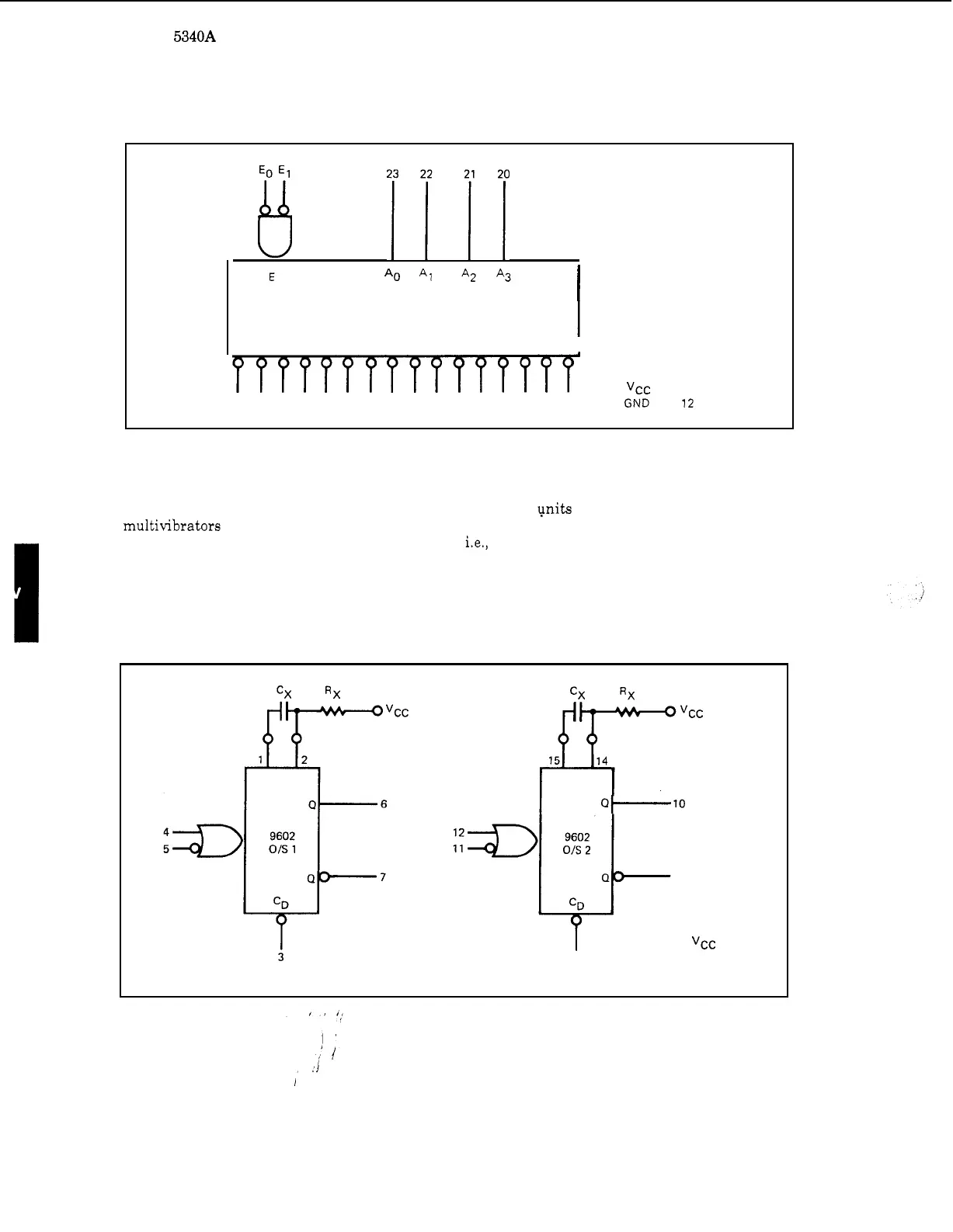
39.
Dual Monostable Multivibrator 1820
-
0515
4
-
40.
The dual multivibrator
is
shown in Figure
4
-
17.
The
pits
are retriggerable and resettable
multivibrators which provide an output pulse whose duration
is
a
function of the external timing
components. The inputs are dc level sensitive;
i.e., triggering occurs on the rising or trailing
edges of the input waveform. Successive inputs with
a
period shorter than the delay time will
retrigger the one
-
shot resulting in
a
continuous true output. The output pulse may be terminated
at
any time by applying
a
low logic level to the reset input.
Figure
4
-
17.
Dual Monostable Multivibrator
1820
-
0515
at-to
13
9
Vcc
=
Pin
16
GND
=
Pin
8
4
-
12