Model 5340A
Operation
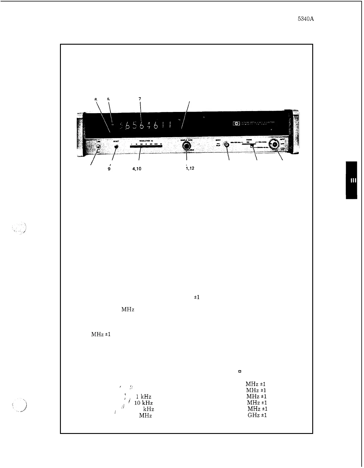
Figure
3
-
6.
Self Check and Operational Check Procedures
7
8
-
-
/
I
.‘I
I
\
\
\
1.
2.
3.
4.
5.
6.
7.
8.
9.
10.
I
1
9’
4,lO
3.1
i.12
13
2
15
Set LINE switch to on (up) position.
Set RANGE switch to CHK position.
Rotate SAMPLE RATE control fully ccw.
Set RESOLUTION switch to
1
Hz.
Check that DIR annunciator lights.
Check that GATE light flashes.
Check that display indicates
10.000000
*1
count.
Check that
MHz annunciator lights.
Press and hold RESET switch, DIR and GATE lights should go out and display
should be
00.000000.
Release RESET switch, check that display is
10.000000
MHz
*l
count.
Change RESOLUTION switch to the following positions and check for proper
display. When the switch is in between positions, the DIR light and GATE light
should go
out
and the display should reset (all zeros).
RESOLUTION Switch
DISPLAY
(B
Blank Display Tube)
10
Hz
100
Hz
’
lkHz
’
i
10kHz
’’
100
kHz
1
MHz
’
;!
I
B1O.OOOOO
MHz
*l
count
BB1O.OOOO
MHz
*1
count
BBB1O.OOO
MHz
*l
count
BBBB1O.OO
MHz
*1
count
BBBBB1O.O
MHz
*1
count
BBBBB.O1O
GHz
*1
count
3
-
9