Model 5340A
Theory of Operation
4
-
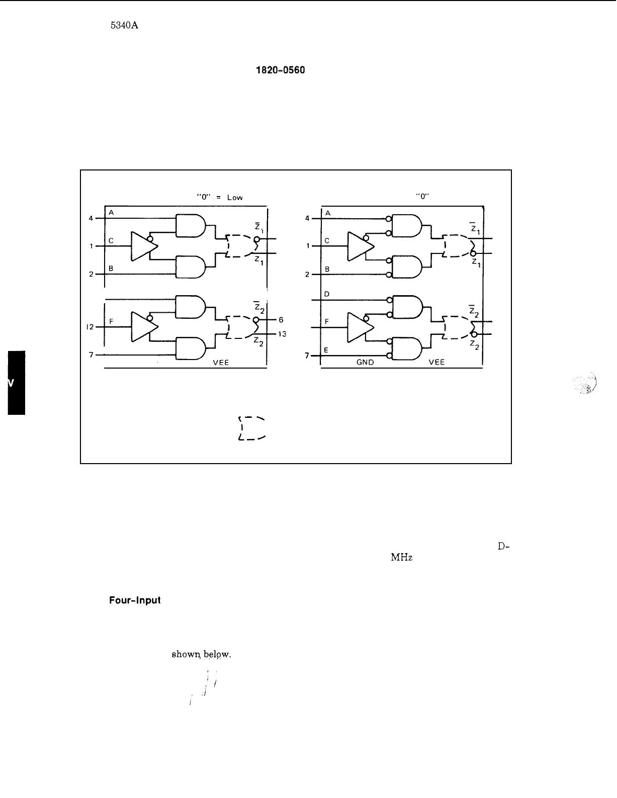
45. Dual Two
-
Input Logic Switch 1820-0560
4
-
46. The logic switch (Figure 4
-
20) functions
as
a
single pole, double throw switch for EECL
logic signals. The C input controls selection of either the A or
B
input; similarly, the
F
input
controls the D and E input selection. Complementary
50
ohm outputs are provided from the out
-
put gates.
Figure 4
-
20. Dual Two
-
Input Logic Switch 1820
-
0560
POSITIVE LOGIC
"
1
"
=
High
"0"
=
Low
.
3
14
I
D
5,
-
E
7
GND
NEGATIVE LOGIC
"
1
"
=
Low
"0"
=
High
,
1
5
12
7
3
14
6
13
I
16
I
11
<-
1
I
I
16 11
NOTE:
)
=
Virtual Gate, No Delay
L,/
4
-
47. Dual D
-
Type Edge
-
Triggered Flip
-
Flops 1820
-
0596
4
-
48.
This IC contains low
-
power dual edge
-
triggered flip
-
flops
as
shown
in Figure
4
-
21.
Infor
-
mation
at
the D
-
input
is
transferred to the
Q
output on the positive
-
going edge of the clock pulse.
Clock triggering occurs at a voltage level
of
the clock pulse and
is
not directly related to the
transition time
of
the positive
-
going pulse. When the clock
is
at
either
a
high or low level, the D-
input signal has no effect. Maximum clock frequency
is
typically
3
MHz with
a
typical power
dissapation of 4.25 milliwatts per flip
-
flop.
4
-
49. Four-Input Multiplexer 1820
-
0610
4
-
50. The 1820
-
0610 (Figure 4
-
22) consists of two 4
-
line input multiplexers with common input
select logic. This configuration allows two bits of data to be switched in parallel to the approp
-
riate outputs from two 4
-
bit data sources. Complementary outputs are provided. The truth table
for the multiplexer is
show9 belpw.
4
-
14