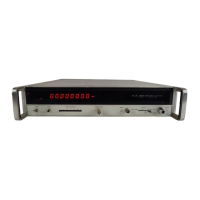
Model
5340A
Theory of Operation
4-196.
U3
operates
as a
differential amplifier with
U5
providing additional gain.
R3,
R13,
and
R16
are terminating resistors for each amplifier. The output of
U5B(ll)
feeds to the first decade
count board
A22.
The amplifier has
a
gain of about
30
dB and
is
dc coupled.
A
stable dc output
level is achieved by feeding back part
of
the output signal via operational amplifier
U1
to the
input of
U3. U1
detects any difference between the average (dc) level of
U5(12)
and the wiper of
Rll.
Any imbalance produces a change in the level
at
Ul(6).
The output of
U1
is used as feed
-
back for the amplifier chain.
C13, C14,
and
R4
give
U1
a
very slow time constant. Keeping the
output stable yields the best sensitivity for the counting circuits on
A22.
4
-
197.
quency response.
possible counting of noise.
R14
provides minor feedback loops within the wideband amplifier to flatten the fre
-
C21
controls the high frequency response of the circuit to eliminate any
4
-
198. U2
circuitry
is
a detector and comparator that determines if
a
signal below
-
225
MHz is
present. If
so,
this will take precedent over energizing the operation of the phase lock mode of
the instrument. The presence of
a
signal causes
CR5
to reduce the positive charge on
C19
obtained through
R21.
This
is
matched by
CR4
and
C20
on the other side of the comparator
U2.
A
low pass filter
(L5)
is
included
in
one leg and
a
high pass filter
(C16, L6,
and
L7)
is
installed in
the other leg of the amplifier inputs.
R18
and
R17
control the response of the detector by
reducing the
Q.
4
-
199.
If a signal exists below
-
225
MHz,
CR5
places
a
voltage on
C19
which is less positive than
that on
C20,
this will flip the comparator to
a
TTL high on
U2(7).
This tells the counter to imple
-
ment the direct count mode. If the signal
is
higher in frequency, the voltage on
C19
will increase
because of filter
L5. The voltage on
C20
will be less positive than before since a greater signal
level
is
coupled through the high pass filter
C16,
L6,
and
L7.
Thus
U2
will flip with pin
7
going to
a
TTL low level, and the instrument will begin phase lock searching.
R22
is
adjusted
so
that only a
signal that
is
strong enough to be counted will flip
U2.
This eliminates unstable displays.
R21
and
R20
keep
a
small amount of current flow through
CR4
and
CR5
to increase the sensitivity of
the detector to small signals that would not normally turn on the diodes.
L1
through
L4
and
associated capacitors are power supply filters. The output signals of
U2
are valid only during
direct count check (Test
#8).
During other times, the outputs of the
VCO’s
(A10
and
A12)
may
cause
A17U2
to incorrectly indicate the presence
of
a
direct count signal.
4
-
200. A18 STANDARD OSCILLATOR ASSEMBLY, 05340
-
60036
4
-
201.
See Figure
8
-
24
for the schematic diagram of
A18.
The temperature compensated crystal
oscillator
(TCXO)
supplies
a
10
MHz sine wave on pins
1
and A for use in the
5340A.
Input power
consists of
+5
and
-
5
volts dc. The
TCXO
is
factory repairable only. Adjustments are contained
in Section
V.
4
-
202.
A18
OPTION
001 OSCILLATOR ASSEMBLY, 10544A
4-203.
It has an
internal oven and controller that maintains
a
constant temperature, with
a
resulting stable output
frequency on pins
1
and
A.
The
10544A
Oscillator (Figure
8
-
24)
is
used when Option
001
is
installed.
4
-
204.
Any
5340A
that
is
wired for Option
001
will work when the standard oscillator
is
installed.
This may be helpful in troubleshooting. To install Option
001
in an instrument not
so
equipped,
;,
see Section VII: The
10544A
is
factory repairable only.
Adjustment procedures are contained
in Section
V.
4
-
205. A19 INTERFACE A ASSEMBLY, 05340
-
60031 AND A27 RESOLUTION SWITCH
ASSEMBLY, 05340
-
60026
I
//
4
-
206.
Interface A Assembly (Figure
8
-
25)
provides the control signals necessary for completing
and displaying a
measuremndnt. The circuitry associated with
U5
selects either the internal
10
MHz oscillator or an extdrnal standard.
U5D,
U5C,
and
R11
form a Schmitt trigger for the
internal oscillator;
U5B1 U5C,
and
R12
are used for the external oscillator.
U2A
and
U2B
serve
as
buffers for the oscillator signal.
4
-
44

 Loading...