Model 5340A
Operation
Figure
3
-
3.
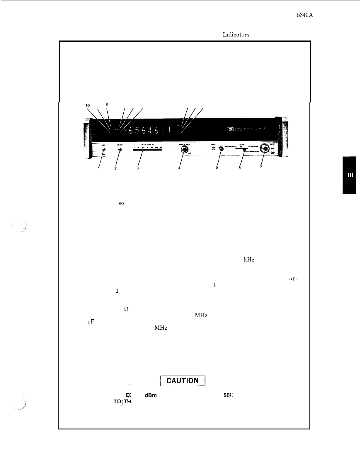
Front Panel Controls and lndicators
10
9
8
11
12
13
14 15
16
1.
LINE switch. Applies primary power to all circuits except crystal oven Option
001,
when
so
equipped. When the counter is equipped with Option
001,
the
crystal oven connects through
a
thermal circuit breaker and fuse to the ac line.
This allows the oven to maintain its operating temperature and accuracy when
the LINE switch is OFF, thereby eliminating warm
-
up delays.
2.
RESET switch.
measurement.
Resets display and internal count to zero and initiates a new
3. RESOLUTION Hz selector. Determines resolution of the measurement. See
Paragraph 3
-
8 for a detailed description.
In general, the
1
kHz setting
is
a good
starting point.
SAMPLE RATE control. Adjusts the interval between measurements from
ap-
proximately
50
milliseconds to 5 seconds. For
1
Hz RESOLUTION settings an
additional
1
second delay is incurred. When rotated to the HOLD position, the
display will be held indefinitely.
BNC
1
MEG
Q
Input Connector. High impedance
(1
Megohm) input for direct
count measurements in the
10
Hz
to
250 MHz range. Shunt input capacity is
25
pF maximum. Measurements made at this input require that the RANGE switch
is set to the
10
Hz
-
250 MHz position.
Sensitivity is
50
millivolts rms and the
coupling is ac.
RANGE switch. Selects input connectors and ranges
as
indicated by the black
leader lines.
When set to the CHECK position, the circuits count the frequency
of the internal clock to verify proper counter operation.
4.
5.
6.
,
,
I,
I
DO NOT EXCE D +30 dBm (1 WATT) INPUT AT THE
500
N CONNECTOR.
DAMAGE
TOjT
sk
E INTERNAL SAMPLERS MAY OCCUR. PLEASE READ
PARAGRAPH 3
-
21
FOR
DETAILS
OF
ACCEPTABLE INPUT LEVELS.
3
-
5