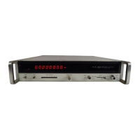
Model 5340A
Table of Contents
I
TABLE
OF
CONTENTS
(Continued)
Section
I
Page
4.194
.
A17A1 Direct Counter Amplifier Assembly.
Od3
0
-
60038
..........
4
-
43
4.200
.
A18 Standard Oscillator Assembly. 05340-60036
..................
4
-
44
4.202
.
A18 Option 001 Oscillator Assembly. 10544&/
....
./
...
r
..............
4
-
44
4
-
205
.
A19 Interface A Assembly, 05340
-
60031 and A27 Resolution Switch
Assembly. 05340
-
60026
...............................
4
-
44
4
-
212
.
4
-
45
4
-
229
.
A20 Time Base Assembly, 05340
--
60073
..........................
4
-
47
4
-
247
.
A22 High Frequency Counter Assembly, 05340
-
60016
.............
4
-
49
4
-
251
.
A23 Counter Register Assembly, 05340
-
60030
.....................
4
-
49
IV THEORY OF OPERATION (Continued)
y
'
A19 Interface B Assembly 05340
-
60032
(Part
of Option 011)
.......
4
-
236
.
A21 Control Assembly, 05340
-
60021
..............................
4
-
48
4
-
255
.
A24 Display Register Assembly, 05340
-
60019
.....................
4
-
50
4
-
258
.
A25 Display Assembly, 05340
-
60020
..............................
4
-
50
4
-
265
.
A26 Blanking Assembly, 05340
-
60037
............................
4
-
51
4
-
267
.
Power Supplies
...................................................
4
-
51
(Part
of Option 001)
..................................
4
-
51
4
-
269
.
4
-
273
.
A32
+5
Volt Regulator Assembly, 05340
-
60023
................
4
-
52
4
-
278
.
A29
+15
Volt Regulator Assembly, 05340
-
60025
...............
4
-
53
4
-
280
.
A28
-
15
Volt and +175 Regulator Assembly, 05340
-
60022
......
4
-
53
4
-
283
.
A31
-
5
Volt Regulator Assembly, 05340
-
60024
.................
4
-
54
4
-
285
.
A34 Bus Communicator Assembly, 05340
-
60067
(Part
of Option 011)
..................................
4
-
54
4
-
287
.
Talk Mode
...................................................
4
-
54
4
-
290
.
Listen Mode
..................................................
4
-
54
A33 Optional Oscillator Power Supply Assembly, 05340
-
60039,
V MAINTENANCE AND SERVICE
........................................
5
-
1
5.1
.
Introduction
......................................................
5
-
1
5.3
.
Assembly Designations
...........................................
5
-
1
5.5
.
Test Equipment
..................................................
5
-
1
5.7
.
Pozidriv Screwdrivers
............................................
5.1
.
5.9
.
Adjustments and In
-
Cabinet Performance Check
.................
5
-
1
5.11
.
Blower Fan Configuration
........................................
5-1
5.13
.
K05
-
5340A Description
...........................................
5
-
1
5.16
.
Program Control Flow Diagrams
.................................
5
-
14
5.24
.
Overall Troubleshooting
..........................................
5
-
17
5.26
.
A20 N Checker Troubleshooting
..............................
5
-
18
5.35
.
A21 Troubleshooting
.........................................
5
-
19
5.39
.
Power Supply Troubleshooting
...............................
5
-
20
VI REPLACEABLE PARTS
.................................................
6
-
1
6.1
.
Introduction
......................................................
6
-
1
6.4
.
Ordering Information
............................................
6
-
3
6.7
.
HP
Part
Number Organization
...................................
6
-
3
6.9
.
Component
Parts
and Materials
..............................
6
-
4
6.12
.
General Usage
Parts
.........................................
6
-
4
6.14
.
Specific Instrument
Parts
....................................
6
-
4
VII MANUAL CHANGES AND OPTIONS
...................................
7
-
1
7.1
.
Introduction
......................................................
7
-
1
7.5
.
New Instruments
.............................................
7
-
1
7
-
7
.
Older Instruments
.............................................
7
-
1
7
-
9
.
Options
..........................................................
7
-
16
7
-
11
.
Option 001, High
-
Stability Oscillator
.........................
7
-
16
7
-
13
.
Option 002, Rear Panel Connectors
...........................
7
-
16
7
-
15
.
Option 011, Remote Programming
and
Digital Output
.........
7
-
16
7
-
19
.
Field Installation of Options
......................................
7
-
16
7
-
20
.
Installation of Option 001, High
-
Stability Oscillator
..........
7
-
16
7.3
.
Manual Changes
.................................................
7
-
1
iv

 Loading...