Model 5340A
Theory
of
Operation
Figure 4
-
28. Low
-
Power BCD Decade Counter
1820
-
0669
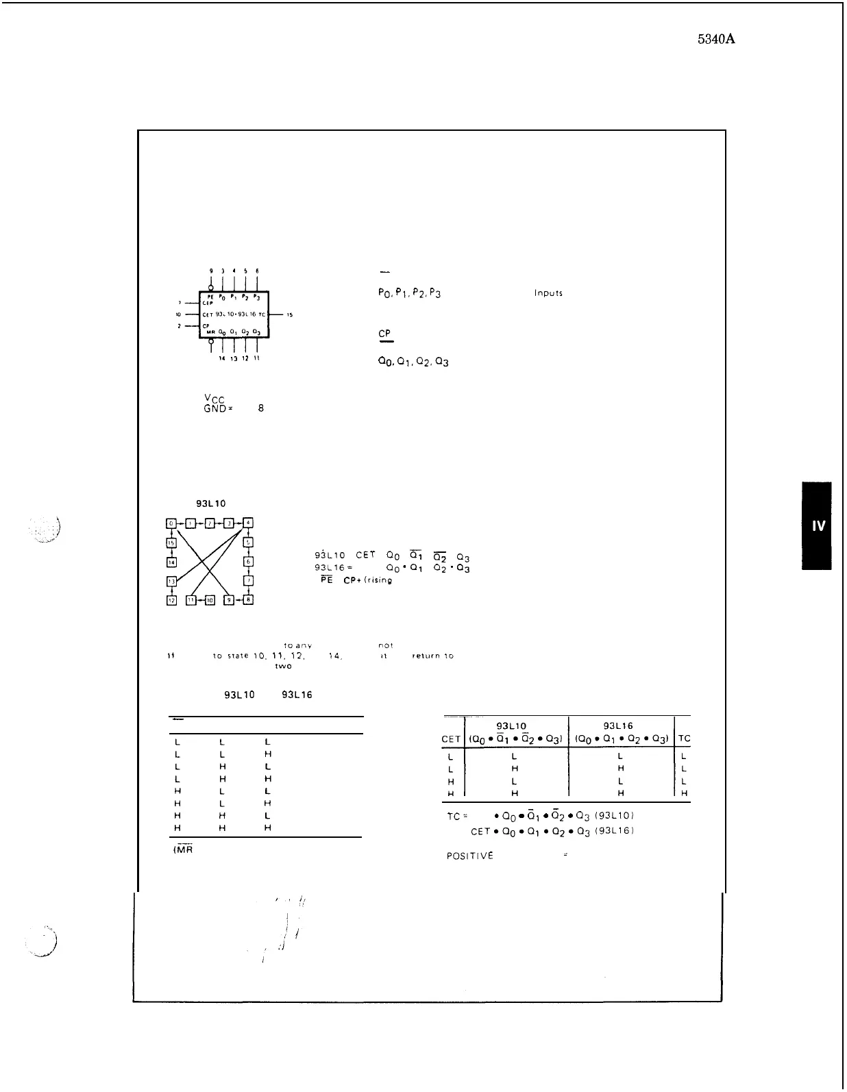
LOGIC SYMBOL
93456
,
1.
I,
12
II
PIN NAMES
PE
-
Po.
p1.
p2. p3
CEP
CET
CP
MR
00.
01,
Q2.
03
TC
-
VCC
=
Pin
16
GND= Pin
0
STATE DIAGRAM
93L10
LOGIC EQUATIONS
Count Enable
=
CEP
.
CET
.
PE
TC
for
95~10
=
CET
.
a.
.
.
Cj
.
03
TC
for
93L16
=
CET
.
Qo
'
01
.
02
'
03
Preset
=
Reset
=
.
CPt
(rising
clock
edge)
NOTE
The
931.10
can
be
preset
to
any
state.
bur
will
not
count
beyond 9
If
preset
10
Irate 10.
11.
12,
13,
14.
or
15.
11
will
relorn
10
its
normal sequence
within
two
clock
pulses
93L10 AND 93L16
MODE SELECTION
-
PE CEP CET
M
O
DE
Preset
Preset
Preset
Preset
No Change
No Change
No Change
Count
(s
=
HIGH)
Parallel Enable (Active LOW) Input
Parallel
Inputs
Count Enable Parallel Input
Count Enable Trickle Input
Clock (Active HIGH Going Edge) Input
Master Reset (Active LOW) Input
Parallel Outputs
Terminal Count Outputs
TERMINAL COUNT GENERATION
TC
=
CET
0
00
rn
61
0
62
0
03
(93LlOl
TC= CET000001002003 (93L16)
POSITIVE LOGIC
=
H
=
HIGH Voltage Level
L
=
LOW Voltage Level
4
-
21