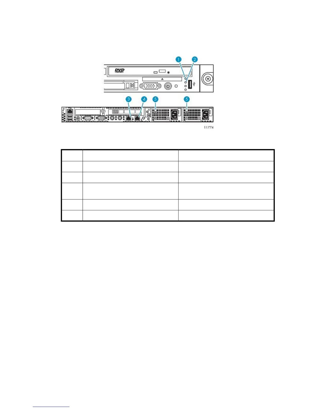
6. Confirm that the VLS components are all functioning normally and the VLS is cabled correctly by
observing the condition of their status LEDs. The LED status should match those shown in the
following table.
If an LED status does not match the status shown in the following table, a component needs
attention.
Figure 41 VLS9000 node LED status during normal operation
.
StatusDescriptionItem
LED is green.Internal health LED1
LED is green.External health LED (power supply)2
LED is green if primary node. LED is off if
secondary node.
NIC 1 link LED3
LED is green.NIC 2 link LED4
LED is green.Power supply LEDs5
7. Rebooting the system is complete when you receive the “Initializing node#”, then “Initializing for
node# completed.” messages for all nodes in the systems notifications.
Rebooting the System
To reboot the system from VLS CLI:
1. Verify that any backup or restore operation has completed and that the VLS is idle.
2. Open a secure shell session and log in as the administrator. See
“Opening a Secure Shell Session” on page 146.
3. Initiate a reboot of the VLS by entering:
restartSystem
To reboot the system from Command View VLS:
1. Verify that any backup or restore operation has completed and that the VLS is idle.
2. Open a Command View VLS session and log in as the administrator. See
“Opening a Command View VLS Session from a Web Browser” on page 143.
3. Under the System tab, select Chassis in the navigation tree.
HP StorageWorks 137
 Loading...


