Cabling Disk Array Enclosures
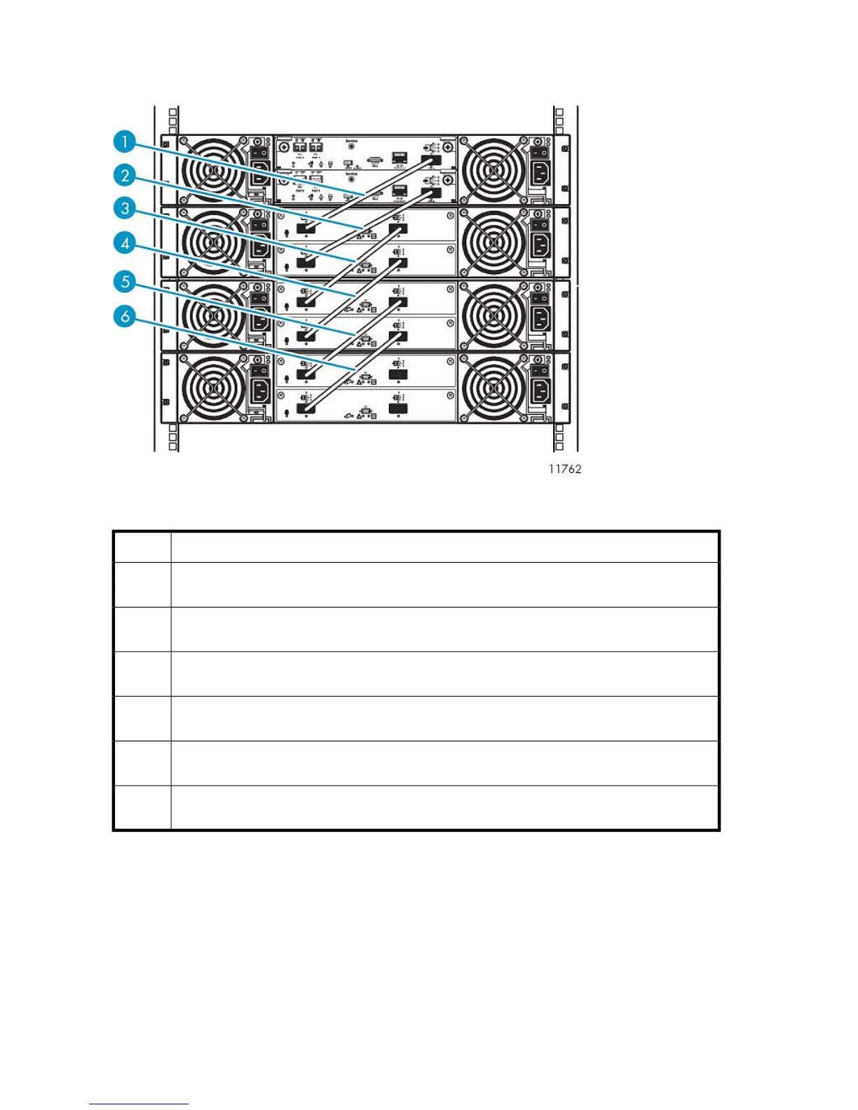
Figure 17 Disk array enclosure SAS port cabling
.
DescriptionItem
SAS cable, SAS port 0 of RAID controller 0 of base disk array connects to SAS port 0, input port,
of expansion controller 0 of expansion disk array 0
1
SAS cable, SAS port 0 of RAID controller 1 of base disk array connects to SAS port 0, input port,
of expansion controller 1 of expansion disk array 0
2
SAS cable, SAS port 1, output port, of expansion controller 0 of expansion disk array 0 connects
to SAS port 0, input port, of expansion controller 0 of expansion disk array 1
3
SAS cable, SAS port 1, output port, of expansion controller 1 of expansion disk array 0 connects
to SAS port 0, input port, of expansion controller 1 of expansion disk array 1
4
SAS cable, SAS port 1, output port, of expansion controller 0 of expansion disk array 1 connects
to SAS port 0, input port, of expansion controller 0 of expansion disk array 2
5
SAS cable, SAS port 1, output port, of expansion controller 1 of expansion disk array 1 connects
to SAS port 0, input port, of expansion controller 1 of expansion disk array 2
6
Locate the SAS cables included in the array kit contents.
Remove the tape and end caps from the SAS cables before installing.
Verify that both power switches are off for each disk array enclosure in the rack.
Starting at the enclosure immediately below Ethernet Switch 2810–24G:
1. Connect one end of a SAS cable to RAID controller 0 of the base disk array enclosure. Connect
the other end to SAS input port of expansion controller 0 of expansion disk array enclosure 0.
Hardware Installation60