2. Locate the AC power cords.
IMPORTANT:
Equally distribute the current between the PDMs.
3. Connect a black power cable to the left power supply of each enclosure and into a PDM mounted
on the left vertical post
4. Connect a gray power cable to the right power supply of each enclosure and into a PDM mounted
on the right vertical post.
Installing VLS9000 Cables
To install VLS9000 cables, follow the instructions in the order of the sections presented below.
Cabling the Nodes
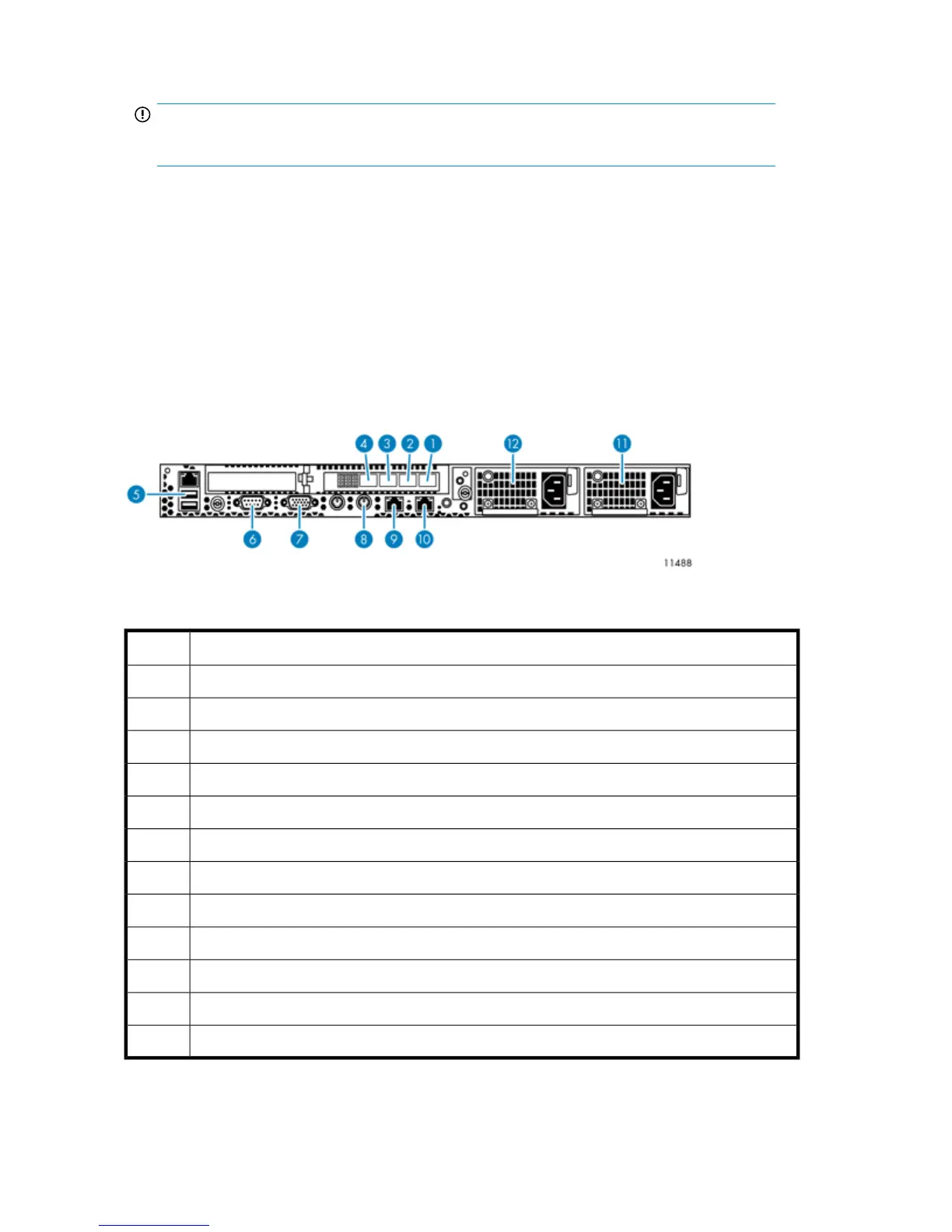
Figure 16 Nodes port cabling
.
DescriptionItem
FC host port, port 11
FC host port, port 22
FC storage port, port 3, on primary node connects to port 0 of Fibre Channel switch #13
FC storage port, port 4, on primary node connects to port 0 of Fibre Channel switch #24
USB connector, on primary node connects to USB/Ethernet adapter, then to port 1 of switch 2510–245
Serial connector to access CLI6
Video connector7
Keyboard connector8
NIC 1, on primary node only connects to the customer-provided external network9
NIC 2, on primary node connects to port 1 of switch 2810–24G10
Power supply 111
Power supply 212
Hardware Installation58