Fibre Channel Switch 4/10q #2
DescriptionItem
FC cable from FC port 0 of RAID controller 1, 2nd — 5th arrays (if present)6—9
FC cable from FC port 0 of RAID controller 1 of 1st array (array 0)10
Ethernet cable from port 23 of Ethernet Switch 2810–24G11
Locate the Fibre Channel cables from the array kit contents.
1. Connect one end of a Fibre Channel cable to Fibre Channel port 9 of Fibre Channel Switch
4/10q #1. Connect the other end of the Fibre Channel cable to Fibre Channel port 0, of RAID
controller 0, of first array (array 0).
2. Connect one end of a Fibre Channel cable to Fibre Channel port 9 of Fibre Channel Switch
4/10q #2. Connect the other end of the Fibre Channel cable to Fibre Channel port 0 of RAID
controller 1 of first array (array 0).
3. With multiple arrays:
a. Working backwards from the last Fibre Channel port on Fibre Channel switch #1, connect
one end of a Fibre Channel cable to the next available Fibre Channel port on Fibre Channel
switch #1. Connect the other end of the Fibre Channel cable to Fibre Channel port 0 of
RAID controller 0 of second array (array 1).
b. Working backwards from the last Fibre Channel port on Fibre Channel switch #2, connect
one end of a Fibre Channel cable to the next available Fibre Channel port on Fibre Channel
switch #2. Connect the other end of the Fibre Channel cable to Fibre Channel port 0 of
RAID controller 1 of second array (array 1).
4. Repeat steps 3 and 4 for all arrays.
5. Secure the Fibre Channel cables installed in this procedure, and the Ethernet cables installed in
the previous procedure together with Velcro ties. Route them to the right side of the rack.
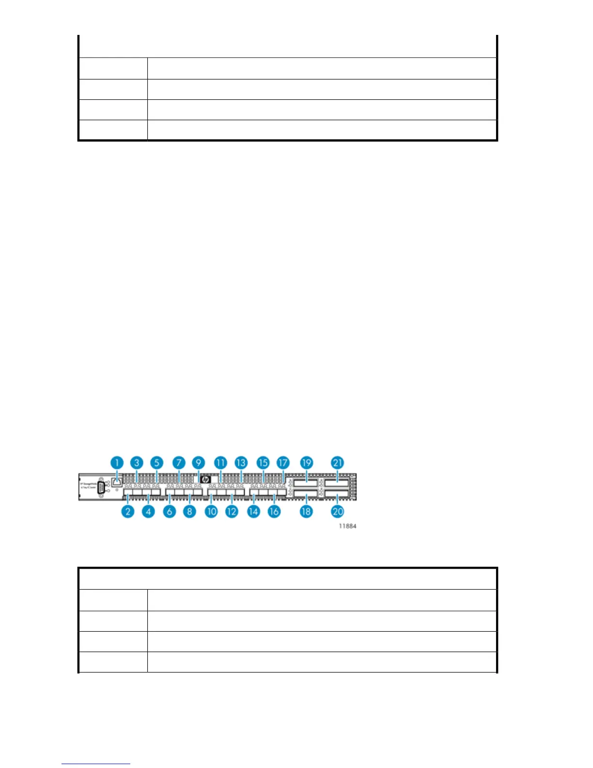
Cabling Fibre Channel Switch 4/16q
Figure 21 Fibre Channel Switch 4/16q port cabling
.
Fibre Channel Switch 4/16q #1
DescriptionItem
Ethernet cable from port 23 of Ethernet Switch 2510–241
FC cable from port 3 of primary node2
FC cable from port 3 of 2nd — 6th nodes (if present)3—7
Hardware Installation64