4. Secure Fibre Channel cables to one side of the rack with a Velcro® tie.
Installing Interswitch Ethernet Cables
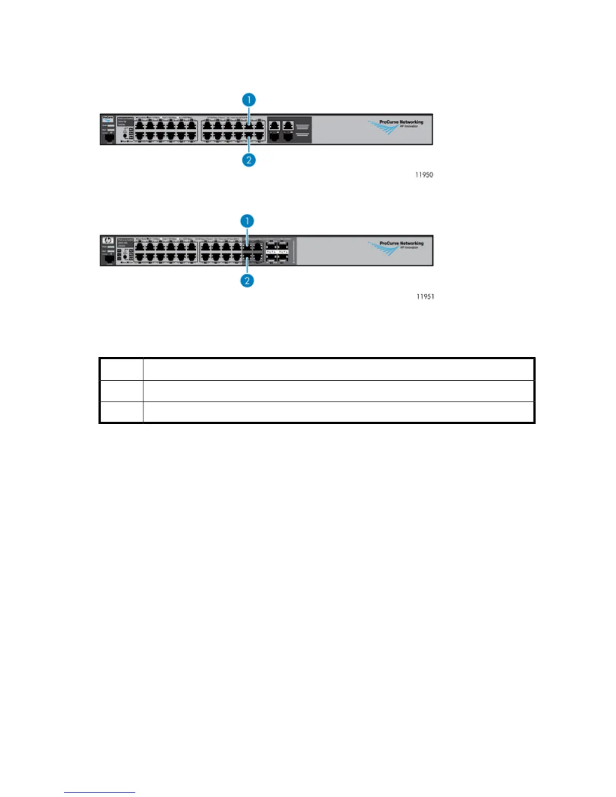
Figure 26 Ethernet Switch 2510–24
.
Figure 27 Ethernet Switch 2810-24G
.
The following table applies to both Ethernet switches shown in Figure 26 and Figure 27.
DescriptionItem
Port 211
Port 222
1. Locate the Ethernet cables included in the interswitch link kit contents.
HP StorageWorks 71