DescriptionItem
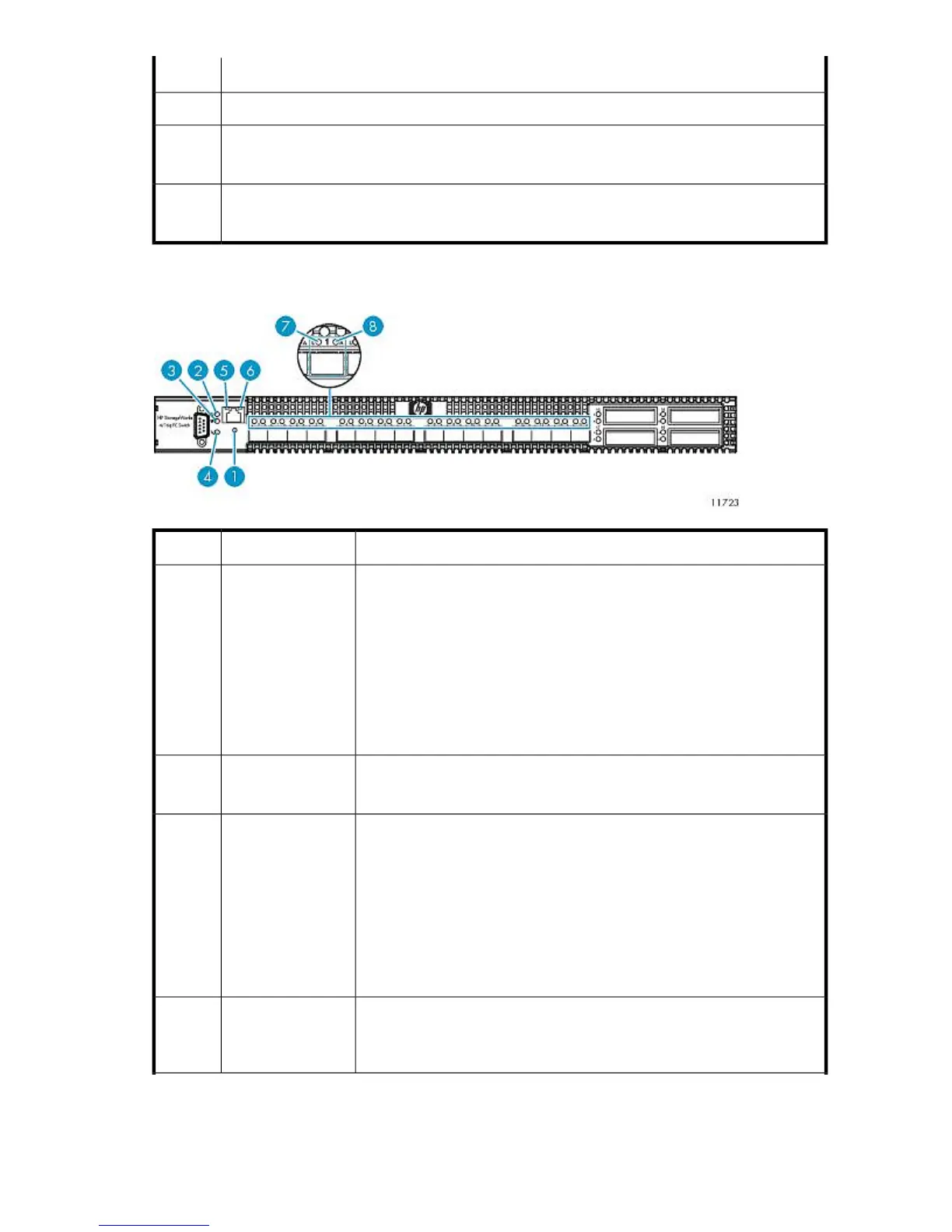
Ethernet port2
4 GB FC ports, port 0 through 15
(numbered from left to right)
3
10 GB FC ports, port 16 through 19
(not used)
4
Front Panel LEDs and Buttons
StatusDescriptionItem
Dual-function momentary switch. Its purpose is to reset the switch or to place
the switch in maintenance mode.
To reset the switch, use a pointed tool to momentarily press and release (less
than 2 seconds) the Maintenance button. The switch will respond as follows:
1. All the chassis LEDs will illuminate except the System Fault LED.
2. After approximately 1 minute, the power-on self test (POST) begins, ex-
tinguishing the Heartbeat LED.
3. When the POST is complete, the Input Power LED is illuminated and the
Heartbeat LED is flashing once per second.
Maintenance button1
Green = Switch logic circuitry is receiving the proper DC voltages.
Off = Switch is in maintenance mode.
Input power LED2
Green = Switch is in maintenance mode.
Blinking green (constant 1 Hz) = Switch passed the POST and the internal
switch processor is running.
2 blinks = Internal firmware failure.
3 blinks = System error.
4 blinks = Configuration file system error.
5 blinks = Over temperature.
See Heartbeat LED Blink Patterns for more information.
Heartbeat LED3
Amber = A fault exists in the switch firmware or hardware. Fault conditions
include POST errors and over temperature conditions.
Off = Switch is operating normally.
System fault LED4
HP StorageWorks 239