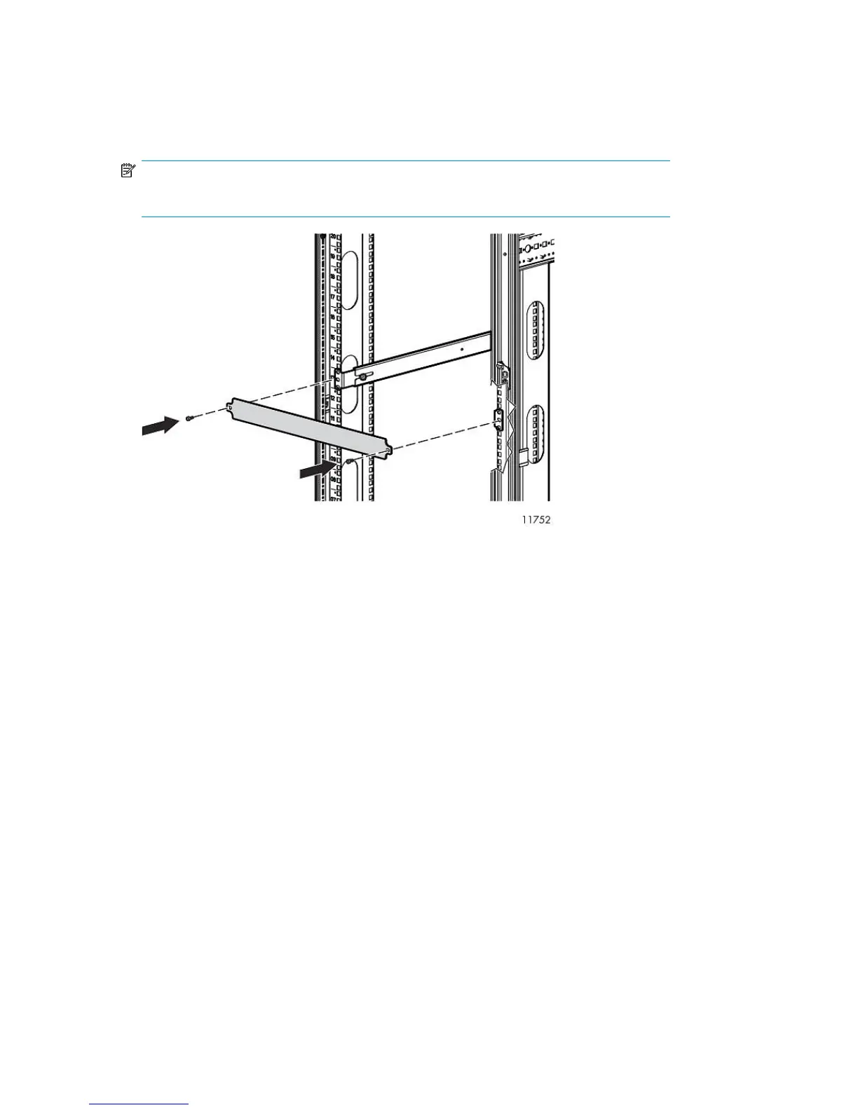
5. Attach two 1U cover plates to the front of the rack.
Attach one 1U cover plate in front of each Fibre Channel Switch 4/16q.
Attach one in front of the Fibre Channel Switches 4/10q and one over the blank space above
the Fibre Channel Switches 4/10q.
NOTE:
With Fibre Channel Switch 4/10q, a blank space is reserved for future expansion.
6. Plug the AC power cords into an AC power source.
Route one cord to a PDM mounted on the right vertical post, and the other to a PDM on the left
vertical post.
Installing the 1 Gb Ethernet Switch 2810–24G into a Rack
Installing the switch into the rack involves installing the cage nuts and rail flanges, attaching the rails
to the switch, and installing the switch into the rack.
Hardware Installation46