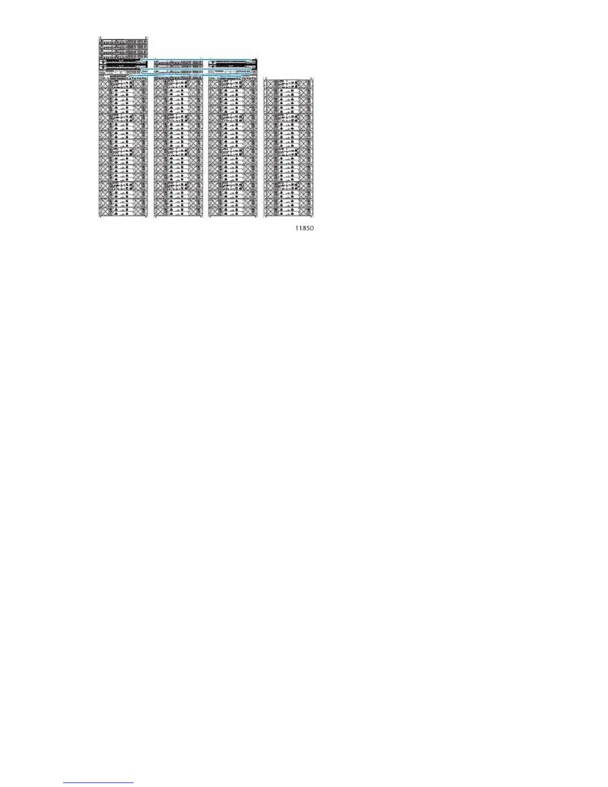
Figure 22 Inter-rack connected VLS9000
.
Reconfiguring Fibre Channel Switches 4/16q
Before installing the interswitch kit, establish a command-line interface (CLI) session with each switch
in rack 3 to ensure that the switches auto-negotiate to the correct domain IDs.
1. Locate a null-modem (serial) cable provided with the VLS.
2. Connect one end of the serial cable to a PC or workstation and the other to the serial port on
the rear of Fibre Channel switch 0 in rack 3.
3. Establish a CLI session using a terminal emulation program, such as Windows Hyperterminal™.
4. At the prompt, select a baud rate of 9600 with 8 data bits and no parity.
5. At the username request, enter admin.
6. At the password request, enter password. The screen displays system information.
7. At the command line, which reads 4/16q FC switch #, enter admin start.
8. Enter config edit. The screen indicates that the default config is being edited.
9. At the command line, enter set config switch. A list of attributes and their values displays.
10. Press Enter until you reach the attribute DomainIDLock.
11. If DomainIDLock is set to True, enter False.
12. Press Enter until you return to the command line.
13. Enter config save. The screen indicates that the default config is saved.
14. At the command line, enter config activate. This activates the config with the attribute values
specified.
15. A prompt asks you to confirm the config activation. Enter y.
16. Enter reset.
17. Enter quit.
18. Repeat this procedure for Fibre Channel switch 1 in rack 3.
HP StorageWorks 67