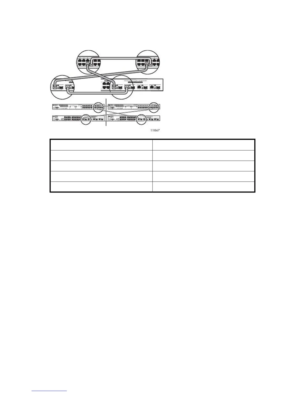
2. Connect the Ethernet cables from the switches in rack 1 to the switches in rack 3. See also Figure
26.
Rack 3Rack 1
To Rack 3From Rack 1
Switch 2510–24 port 22Switch 2510–24 port 22
Switch 2810–24G port 22Switch 2810–24G port 22
Switch 2810–24G port 21Switch 2510–24 port 21
Switch 2510–24 port 21Switch 2810–24G port 21
3. Secure Ethernet cables to the right side of the rack using a Velcro® tie.
Hardware Installation72