Shenzhen Hpmont Technology Co., Ltd. Chapter 7 Elevator Application Guidance
HD5L-PLUS Series User Manual V1.0 77
Chapter 7 Elevator Application Guidance
It is recommended to analyze the actual application requirements before the wiring design.
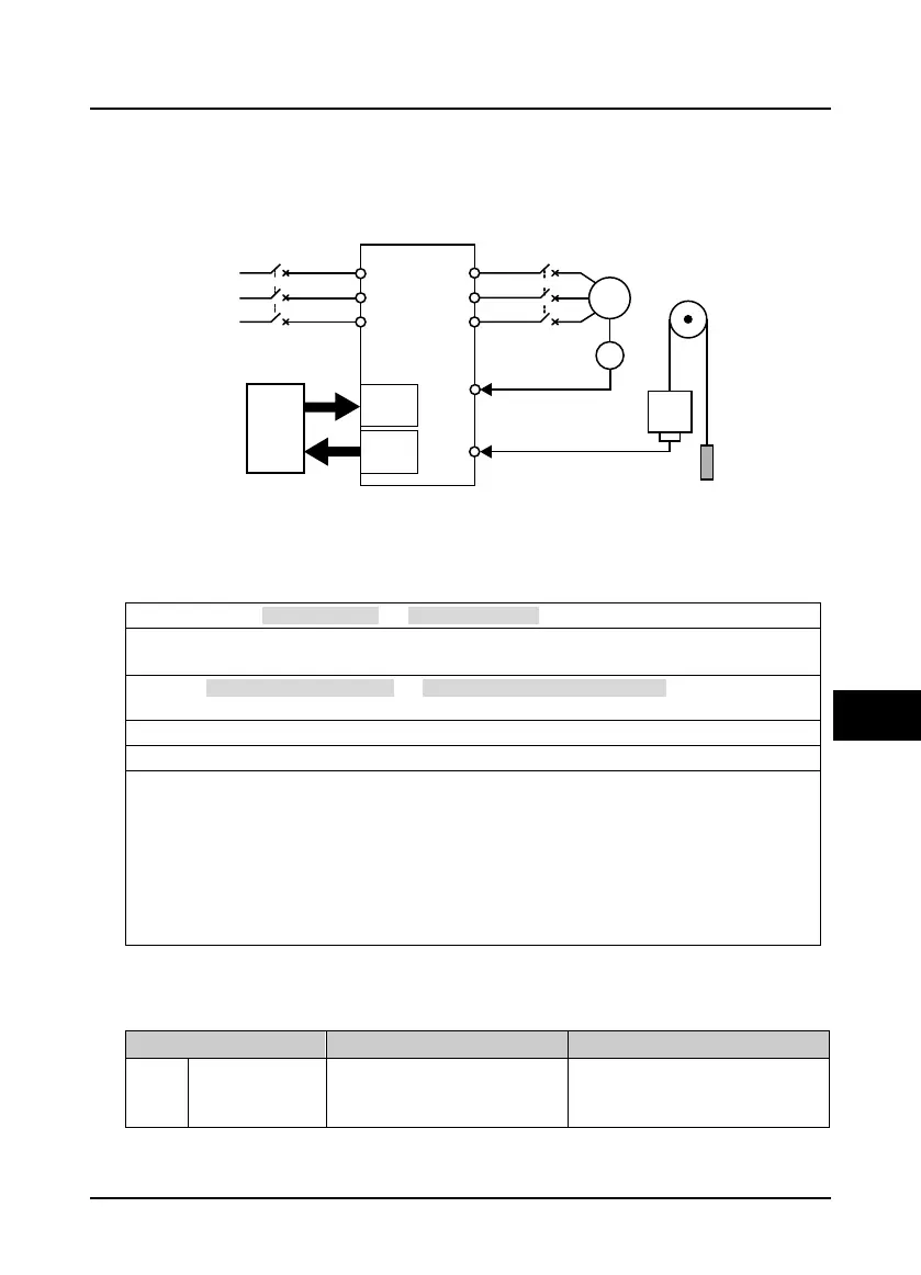
Basic configuration for elevator system with HD5L-PLUS is shown in Figure 7-1.
Figure 7-1 Elevator system
7.1 Basic Debugging Procedures
7.1.1 Set Basic Parameters
1.
Correctly set F00.00 (motor type) and F00.01 (control mode).
2.
Set the relevant parameters of the motor.
• Set group F07 for the Asyn. motor, set group F10 for the Syn. motor.
3. Set F00.02 (rated speed of elevator) and F00.04 (mechanical parameters of motor) according to the
elevator requirement and motor parameters.
4. Set the group F11 parameters (encoder) according to the encoder configured to motor.
5. Set group F12 (digital I/O terminal parameters) according to the actual wiring.
6. Terminal MS running mode (section 7.2):
• Set the parameters of group F05 (MS) according to the elevator demand and elevator controller.
• Set the parameters of group F03 (Acc./Dec.) according to the elevator speed.
Terminal analog running mode (section 7.3)
• Set analog curve parameters of group F04 and analog I/O terminal parameters of group F13
according to the actual requirement of elevator and the controller.
• Set the F03 group parameters as large as possible, so that the HD5L-PLUS can follow the speed
command of the elevator controller at the fastest speed.
7.1.2 Motor Auto-tuning
Auto-tuning Fault (E12) Processing
Fault Fault Reasons Counter-measures
E12
Motor auto-tuning
fault
• Parameter auto-tuning is time out
• Check the motor connection
• Input correct nameplate parameters
• Seek technical support
MCCB
U
V
W
L1
L2
L3
R
S
T
Three phase input power
Contactor
Weigh signal feed
bac
k
(
optional)
Car
Counter
weight
380V 50/60Hz
Elevator
Logic
Control
Board
Input
terminal
Output
terminal
M
PG
Speed feedback
HD5L-PLUS
 Loading...
