Chapter 4 Electrical Installation Shenzhen Hpmont Technology Co., Ltd.
28 HD5L-PLUS Series User Manual V1.0
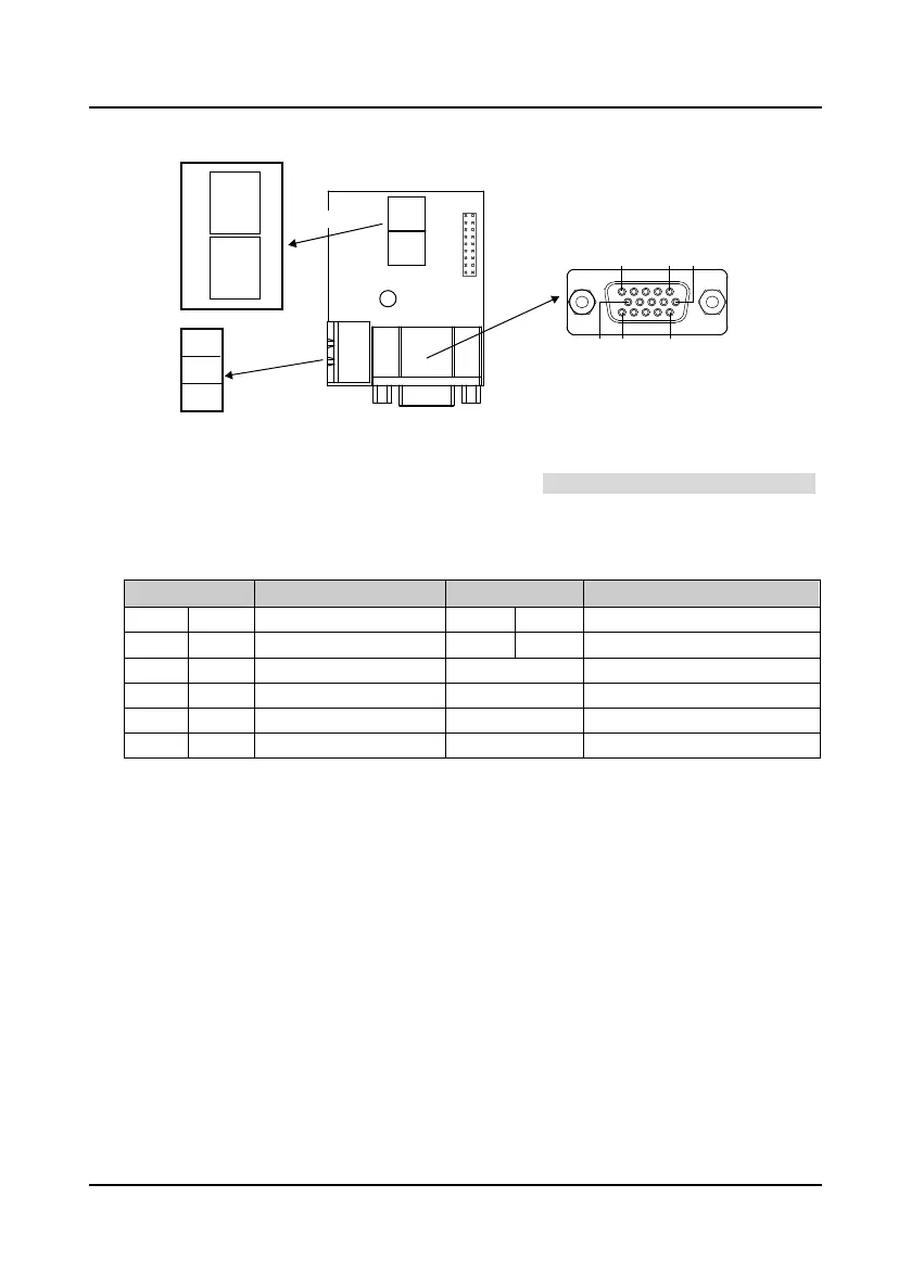
4.5.7 HD-PG6-UVW-FD
Figure 4-18 HD-PG6-UVW-FD
FD Switch
Frequency division switch to set frequency division factor, see section 4.5.3 FD Description, on page 24.
Terminal Description
Connect the DB15 terminal to the DB15 socket of motor encoder signal cable.
Table 4-11 DB15 terminal and FD output terminal description
Terminal Description Terminal Description
1/2 A+/A-
Differential signal A+/A- 13 PGVCC +5V power supply
3/4 B+/B-
Differential signal B+/B- 14 PGGND Power supply ground
5/6 Z+/Z-
Differential signal Z+/Z- 15 Unused
7/8 U+/U-
Differential signal U+/U- OUTA
Output A signal, NPN type OC output
9/10 V+/V-
Differential signal V+/V- OUTB
Output B signal, NPN type OC output
11/12 W+/W-
Differential signal W+/W- COM
Output ground, isolated from GND
COM
OUTA
OUTB
ON
ON
1 2 3
1
2
3
HD-PG6-UVW-FD
6
1
11
5
15
10
DB15
FD
hig
h bi
t
FD
l
ow b
it
F
D ou
t
pu
t
t
e
rm
ina
l
F
D s
wi
t
ch
 Loading...
