Shenzhen Hpmont Technology Co., Ltd. Chapter 4 Electrical Installation
HD5L-PLUS Series User Manual V1.0 27
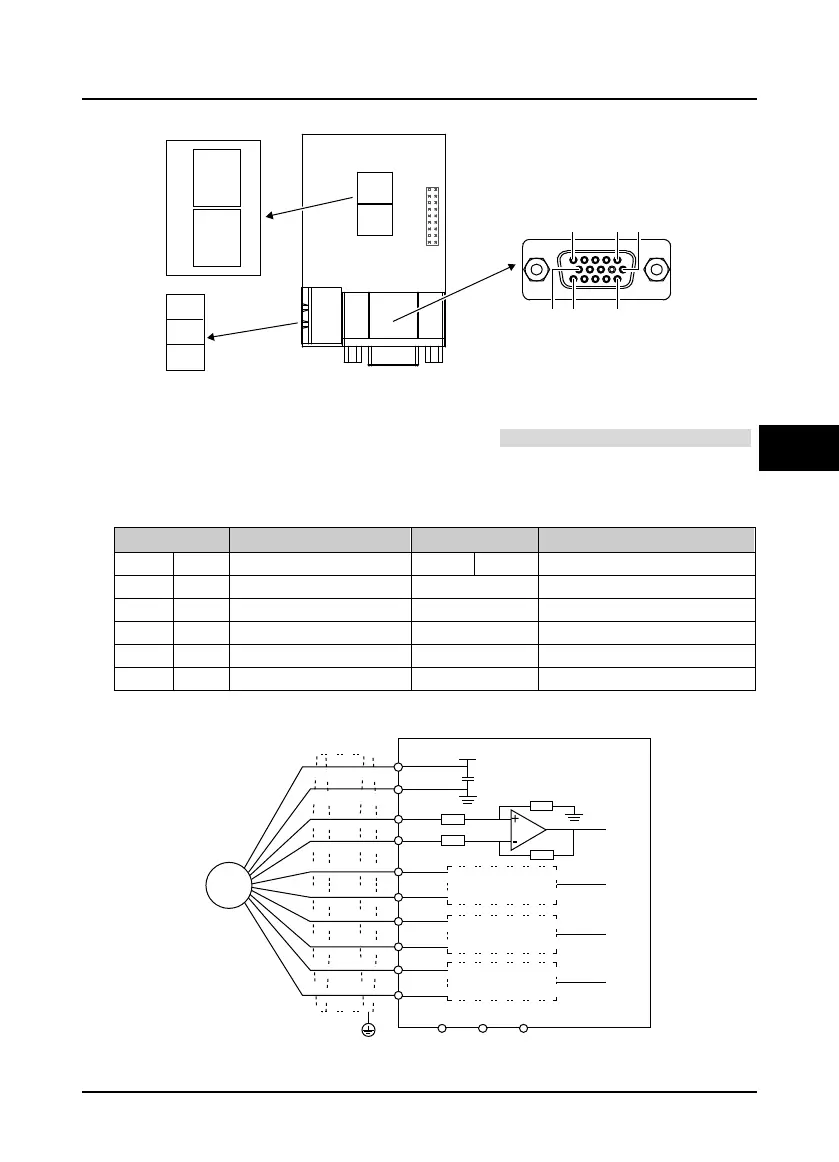
4.5.6 HD-PG5-SINCOS-FD-A
Figure 4-16 HD-PG5-SINCOS-FD-A
FD Switch
Frequency division switch to set frequency division factor, see section 4.5.3 FD Description, on page 24.
Terminal Description
Connect the DB15 terminal to the DB15 socket of motor encoder signal cable.
Table 4-10 DB15 terminal and FD output terminal description
Terminal Description Terminal Description
1/8 B-/B+
Differential signal B-/B+
12/13 D+/D-
Differential signal D+/D-
3/4 R+/R-
Differential signal R+/R- 2/14/15 Unused
5/6 A+/A-
Differential signal A+/A-
7 GND Power supply ground OUTA
Output A signal, NPN type OC output
9 PGVCC +5V power supply OUTB
Output B signal, NPN type OC output
10/11 C+/C-
Differential signal C+/C- COM
Output ground, isolated from GND
Connection
Figure 4-17 Connection of SINCOS encoder
FDswitch
FD output
terminal
COM
OUTA
OUTB
ON
ON
1 2 3
1
2
3
FD
low
bit
FD
high
bit
HD-PG5-SINCOS-FD-A
111510
615
DB15
FD wiring, see
4.5.3
A
GND
GND
SINCOS
encoder
A+
A
-
+5V
GND
OUTA OUTB
PGVCC
B
B+
B-
C
C+
C-
D
D+
D-
COM
PE
PG
Int
erface c
ircuit the
same a
s A
Interface circu
it the
same as A
Interface
circuit the
same as A
HD-PG5-
SINCOS-FD-A
 Loading...
