Chapter 4 Electrical Installation Shenzhen Hpmont Technology Co., Ltd.
26 HD5L-PLUS Series User Manual V1.0
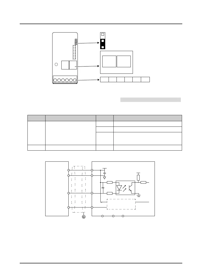
4.5.5 HD-PG2-OC-FD-A
Figure 4-14 HD-PG2-OC-FD-A
FD Switch
Frequency division switch to set frequency division factor, see section 4.5.3 FD Description, on page 24.
Terminal Description
Table 4-9 Terminal description
Terminal Description Terminal Description
PGP
+12V power supply output, jumper
J7 sets the voltage
• Short connect 1,2 pin, 5V
• Short connect 2,3 pin, 12V
(default)
A/B A/B signals of encoder
OUTA Output A signal, NPN type OC output
OUTB Output B signal, NPN type OC output
COM Power ground COM Output ground
Connection
Figure 4-15 Connection of open-collector output encoder
ON
J7
ON
1
2
3
1 2
3
Terminal
F
D switch
ACOMPGP B
OUTB
OUTA
H
D-P
G2-
OC-FD-A
3 1
FD
high
FD l
ow
bit bit
+
5V
A
B
GND
Open
-collector
o
utput
e
ncode
r
A
A
B
B
+12V
C
OM
COM
OU
TA OUT
B
PGP
0V
VCC
COM
PE
Interfacecircuit
thesa
me as A
H
D-P
G2-
OC-
FD-A
FD
wiring,
see
4.5
.3
 Loading...
