Chapter 6 Function Introduction Shenzhen Hpmont Technology Co., Ltd.
46 HD5L-PLUS Series User Manual V1.0
6.1.2 D01: Drive Status Parameters
Ref. Code Function Description Setting Range [Default]
Setting speed (after Acc./Dec.) (m/s)
D01.03 Feedback speed (m/s) [Actual]
Setting frequency (after Acc./Dec.)
D01.10 Output voltage [Actual]
Display output torque which is the relative percentage of the motor rated torque.
Display output power which is the relative percentage of rated power of motor.
D01.14 DC bus voltage [Actual]
6.1.3 D02: Analog Status Display Parameters
Ref. Code Function Description Setting Range [Default]
Display AI input voltage.
AI voltage (after calculating)
Display AI input voltage which is calculated by the gain, bias and filter.
6.1.4 D03: Running Status Parameters
Ref. Code Function Description Setting Range [Default]
D03.00 Heatsink temperature [Actual]
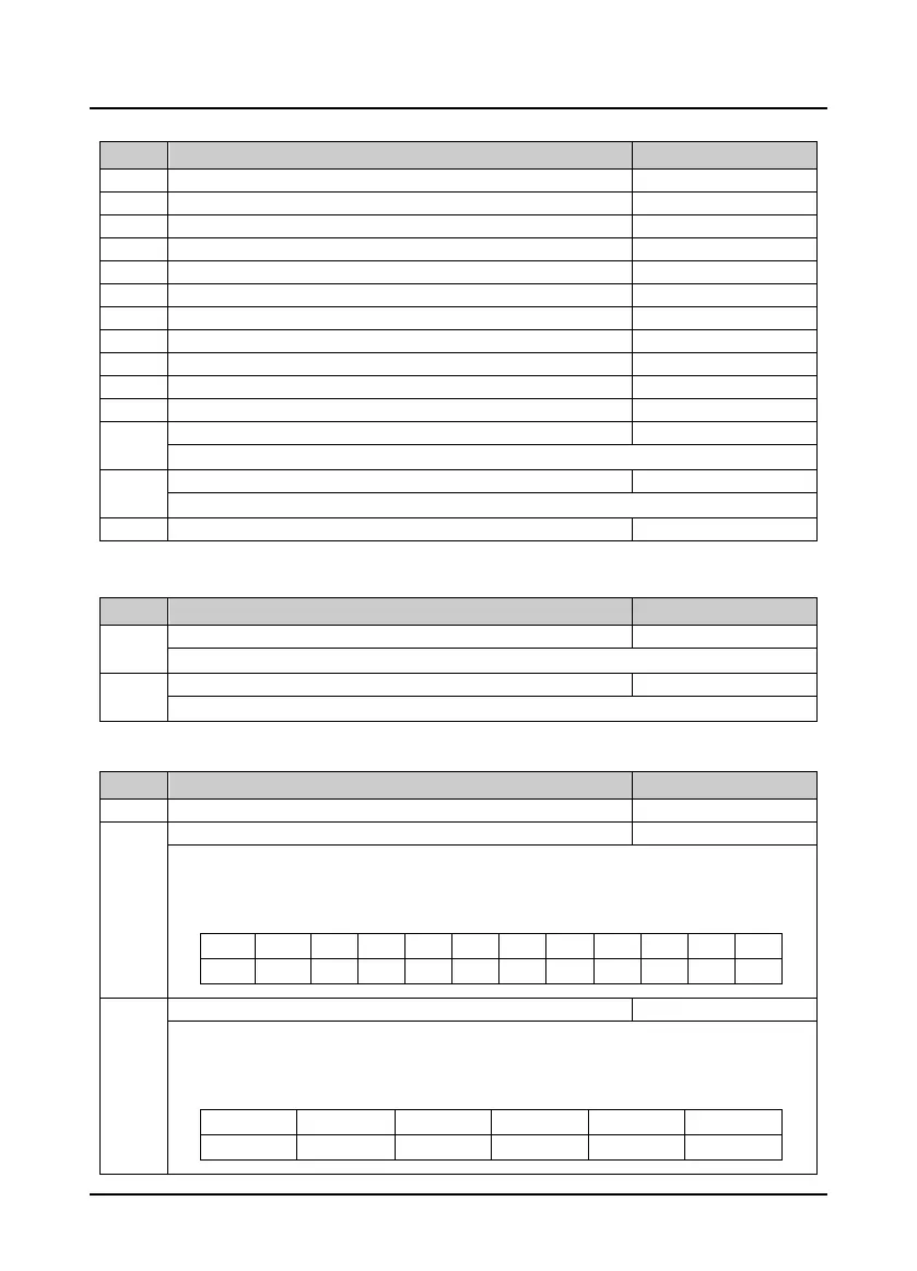
Displays the input terminal status. The corresponding input terminals of each bit (binary) are shown in the
table below.
• 0: Disconnects with common terminals.
• 1: Connects with common terminals.
Bit11 Bit10 Bit9 Bit8 Bit7 Bit6 Bit5 Bit4 Bit3 Bit2 Bit1 Bit0
- - DI10 DI9 DI8 DI7 DI6 DI5 DI4 DI3 DI2 DI1
D03.02 Output terminal status [Actual]
Displays the output terminal status. The corresponding output terminals of each bit (binary) are shown in
the table below.
• Positive logic: 0 stands for invalid while 1 stands for valid.
• Negative logic: 0 stands for valid while 1 stands for invalid.
Bit5 Bit4 Bit3 Bit2 Bit1 Bit0
Y4 (RLY ) Y3 Y2 Y1 DO2 DO1
 Loading...
