Shenzhen Hpmont Technology Co., Ltd. Chapter 4 Electrical Installation
HD5L-PLUS Series User Manual V1.0 17
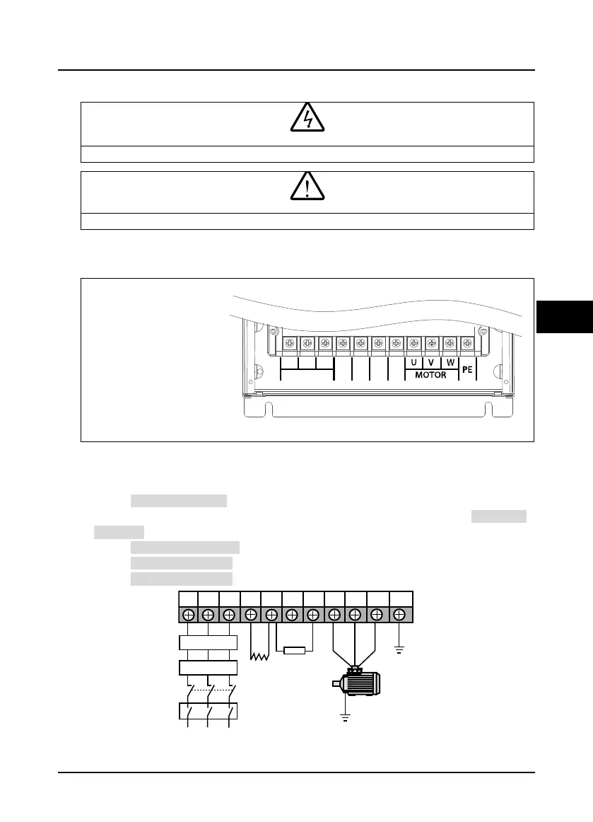
4.3 Power Terminals
• The bare portions of the power cables must be bound with insulation tapes.
• Ensure that AC supply voltage is the same as rated input voltage of HD5L-PLUS.
4.3.1 Power Terminal Description
Table 4-4 Power terminal description
• L1, L2, L3: Three phase AC
power input terminals
• U, V, W: Output terminals,
connect to motor
• P1, (+): DC reactor connection
terminals
• (+), (-): DC supply input
terminals; DC input terminals of
power regenerative unit
• (+), BR: Braking resistor
connection terminals
PE: Ground terminal
4.3.2 Power Terminal Connection
The power terminal connection are shown as Figure 4-1.
• Refer to section 2.5, on page 9 for terminal holes.
• For selection of contactor, MCCB, power cable, motor cable and ground cable, refer to section 4.2.1,
on page 15.
• Refer to section 4.2.2, on page 16 for power terminal lug.
• Refer to section 9.1, on page 93 for braking resistors.
• Refer to section 9.2, on page 94 for AC reactors and DC reactors.
Figure 4-1 Power terminal connection
Contactor
Supply
ground
MCCB
Braking
resistor
Mains supply
L1 L2 L3 (+) (-) BR U V W PE
P1
AC reactor
DC
reactor
EMI filter
 Loading...
