Chapter 4 Electrical Installation Shenzhen Hpmont Technology Co., Ltd.
18 HD5L-PLUS Series User Manual V1.0
4.4 Control Board
• The control circuit is basically isolated with the power circuit. Do not touch HD5L-PLUS after it is powered.
• If the control circuit is connected to external devices with live touchable port, it should increase an additional
isolating barrier to ensure that voltage classification of external devices not be changed.
• If connect the communication terminal of the control circuit to the PC, choose the RS485/232 isolating converter
which meets the safety requirement.
• Only connect the relay terminal to AC 220V voltage signal. Other control terminals are strictly forbiden for this
connection.
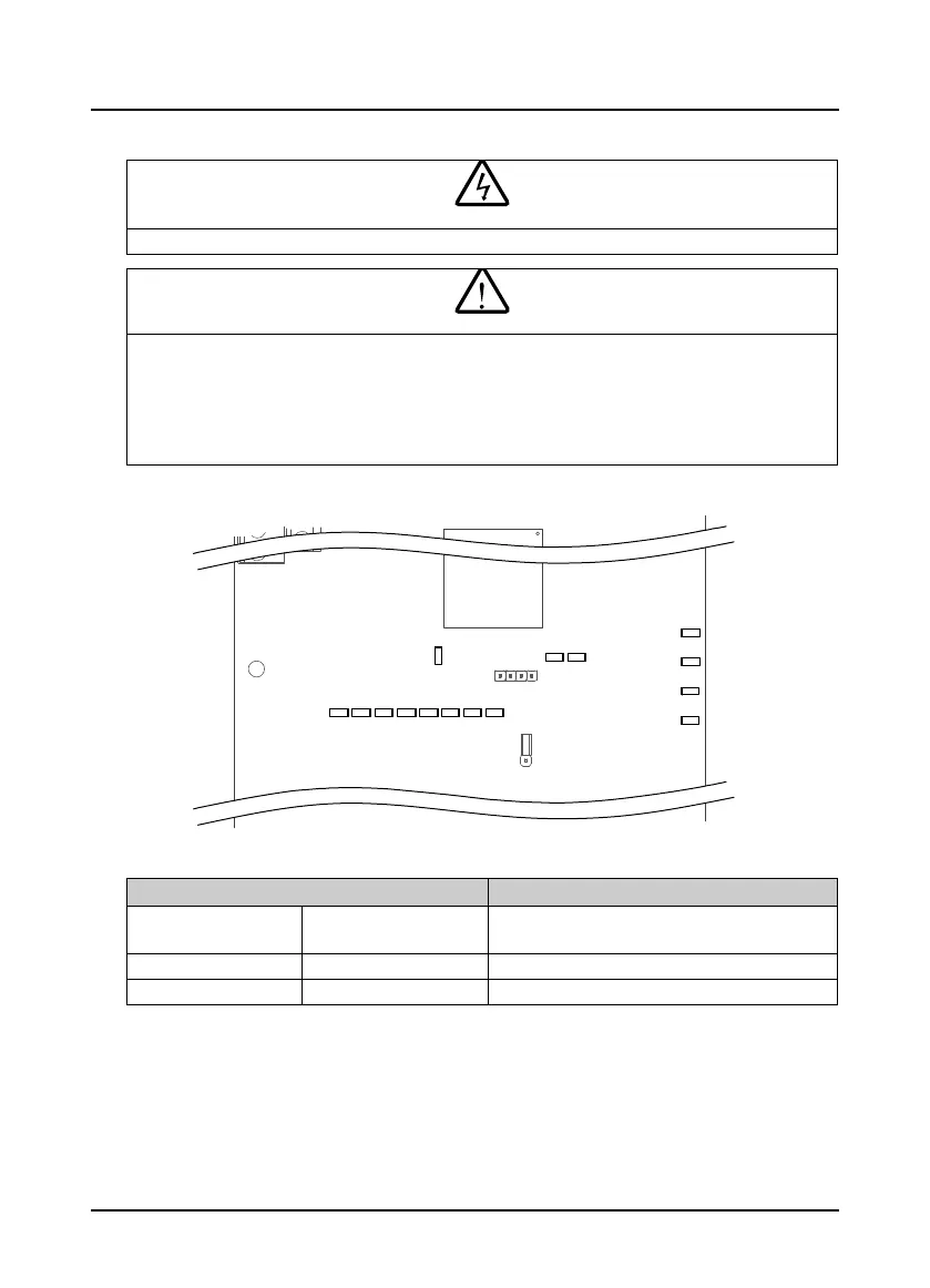
4.4.1 LED Description
Figure 4-2 Indicator
Table 4-5 LED description
Indicator Description
RUN (green) Power Indicator
Flash: Run
On: Stop
DI1 - DI10 (green) Digital input indicator On: Terminal has input
Y1 - Y3, Y4 (RYL) (green) Relay output indicator On: The relay has output
DI1
DI2
DI3
DI4
DI5
DI6
DI7
DI8
DI9 DI10
RUN
Y1
Y2
Y3
Y4
 Loading...
