Shenzhen Hpmont Technology Co., Ltd. Chapter 4 Electrical Installation
HD5L-PLUS Series User Manual V1.0 25
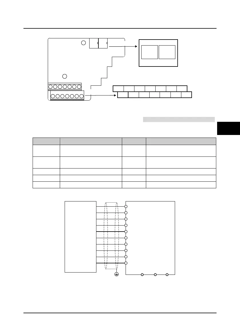
4.5.4 HD5L-PLUS-PG1-SC
Figure 4-12 HD5L-PG1-SC
FD Switch
Frequency division switch to set frequency division factor, see section 4.5.3 FD Description, on page 24.
Terminal Description
Table 4-8 Terminal description
Terminal Description Terminal Description
+5V +5V power supply A+/A-
Encoder differential sine and cosine
analog signal A
GND +5V power ground B+/B-
Encoder differential sine and cosine
analog signal B
CLK+/CLK- Encoder differential clock signal CLK OUTA Output A signal, NPN type OC output
DATA+/DATA- Encoder differential data signal DATA OUTB Output B signal, NPN type OC output
COM Output signal ground, isolated from GND
Connection
Figure 4-13 Serial communication encoder wiring
ONON
1
2
3
1 2
3
FD
high byte
FD
lowbyte
A-GND CLK- DATA- B- COM NC
A+
+5V CLK+ DATA+
B+ OUTBOUTA
HD5L-PG1-SC
FD Switch
Wiring terminals
VCC
0V
A+
A-
B+
B-
CLK+
CLK-
DATA+
DATA-
+5V
GND
A+
A-
B+
B-
CLK+
CLK-
DATA+
DATA-
Series
commu
nicatio
n
encoder
HD5L-PG1-SC
PE
OUTBOUTA
COM
FD wiri
ng, see 4.5.3
 Loading...
