Shenzhen Hpmont Technology Co., Ltd. Chapter 4 Electrical Installation
HD5L-PLUS Series User Manual V1.0 21
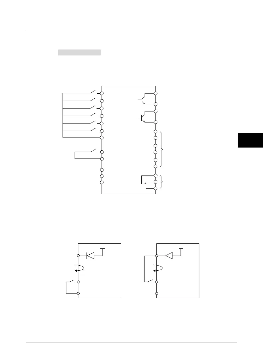
4.4.3 Control Terminal Wiring
Control terminal wiring are shown in Figure 4-4, terminal function is default.
• Refer to section 2.5, on page 9 for terminal holes.
• To reduce the interference and attenuation of control signal, length of control cable should limit
within 50m. There should be more than 0.3m between the control cable and the motor cable.
• The control cable must be shielded cable. The analog signal cable must be shielded twisted pair.
The shield should be reliably grounded.
Figure 4-4 HD5L-PLUS control board connection
Digital Input Connection
Dry Contact
Using the internal 24V power supply, connections are shown in Figure 4-5.
• Short-connect J1 with pin 1,2, low level is valid (default).
• Short-connect J1 with pin 2,3, high level is valid.
Figure 4-5 Dry contact connection
C
on
t
rol board
Controller is running
Controller enabled
Up
Down
Multi-speed 1
Multi-speed 2
Multi-speed 3
Unused
Unused
Unused
DO1
DI1
DI2
DI3
DI4
DI5
DI6
COM
+10V
AI
GND
DI7 - DI10
COM
COM
DO2
COM
RC
RB
Y1
CM1
Y2
CM2
Y3
CM3
RA
Controller is at zero-speed
running
+24V
+24V
COM
P24
Current
K
DI1...DI10
COM
P24
Current
K
DI1...DI10
Using
internal power supply
lowlevel is valid
Using
internal power supply
high level is valid
 Loading...
