3 Configurations and Port
Copyright © Huawei Technologies Co., Ltd.
A board alarm is
generated.
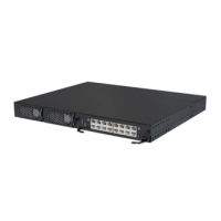
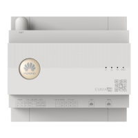
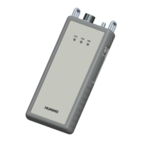
Table 3-11 describes ports on the front panel of the Independent Deployment AI/DI Unit.
Table 3-11 Description of ports on the front panel of the Independent Deployment AI/DI Unit
Cascading ports. COM_IN connects to the RS485 expansion card, and
COM_OUT connects another Independent Deployment AI/DI Unit.
Pin definitions of the ports are the same as those of the COM4 port on
the communication card.
Provide 12 V DC outputs for sensors and are compatible with 4 mA to
20 mA current signals, signals from current-based smoke sensors and
water sensors, dry contact signals, and NTC signals.
Pin definition:
3: 12 V DC, 54 mA
6: D-
7: D+
8: GND
The Independent Deployment AI/DI Unit is configured with a 4-bit DIP switch. Set toggle
switches 1 to 3 to configure the address of the Independent Deployment AI/DI Unit, and set
toggle switch 4 to enable or disable the resistance for the RS485 port. Table 3-12 describes the
mapping between the Independent Deployment AI/DI Unit address and the DIP switch
settings.
Table 3-12 Mapping between the Independent Deployment AI/DI Unit address and the DIP
switch settings
If the signal quality is poor due to signal reflection caused by long communications cables (longer than
50 m), set toggle switch 4 to ON for the furthest independent deployment AI_DI unit. After the DIP
switch settings are modified, power off and restart the independent deployment AI_DI unit for the new
settings to take effect.