Input and Output Option Cable Pin-Out Description 87
User Guide v 1.4 — September 2015 System Options
11.2.3 Input and Output Option Cable Pin-Out Description
Below are the cable connection details for all of the optional Inputs and Outputs. The
connectors are shown as if you were looking at the contact side of the cable.
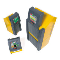
11.3 Altanium I/O Box
The addition of any inputs and outputs that are not supported by the integrated I/O option,
requires an Altanium I/O (Input/Output) box. This box connects to Neo2 via an 8-pin
communications cable. It can also be mounted remotely at the location of your choice.
Table 11-3 Optional Inputs
Option Inputs (female) Pins Wire Colors
Remote Standby Input 1 - 2 green - orange
Remote Boost Input 3 - 4 red - blue
Remote Stop Input 5 - 6 white - black
Table 11-4 Optional Outputs
Option Outputs (male) Pins Wire Colors
Alarm Error Output 1 - 2 green - orange
Abort Error Output 3 - 4 red - blue
At Temperature Output 5 - 6 white - black