Do System Tests to Identify Defective Components
92 810430 Troubleshooting Guide Powermax65/85/105 SYNC
3. Measure the resistance between pin 1 and pin 2 on the power PCB. Is the resistance
approximately 4.7 kiloohms (k)?
If yes, replace the DSP PCB.
If no, replace the power PCB.
Figure 17 – PFC temperature sensor
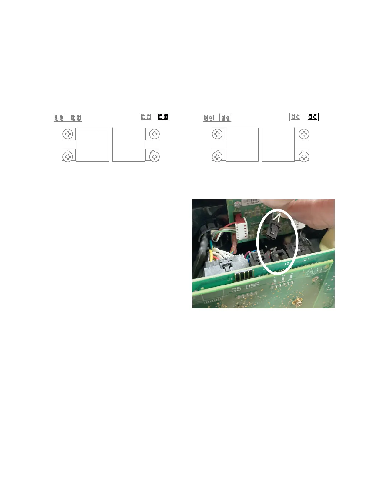
Procedure for fault codes 0-40-2, 0-40-3, 2-10-0, or 2-10-1
1. Disconnect the inverter thermal sensor
from the power PCB, as follows:
J2 in Powermax65/85 SYNC CSA
models
J4 in Powermax65/85 SYNC
CE/CCC models
J2 in all Powermax105 SYNC
models
2. Measure the resistance between pin 1
and pin 3 on the connector. Is the
resistance approximately
10 kiloohms (k) (±1.5 k)?
If yes, continue with the next step.
If no, replace the thermal sensor.
3. Remove the DSP PCB.
4. Keep the thermal sensor disconnected, and measure the resistance between pin 1 and pin 3 on
the power PCB. Refer to Figure 18 on page 93. Is the resistance approximately
57.6 kiloohms (k)?
If yes, replace the DSP PCB.
If no, replace the power PCB.
Powermax65/85 SYNC Powermax105 SYNC