Do System Tests to Identify Defective Components
11 8 810430 Troubleshooting Guide Powermax65/85/105 SYNC
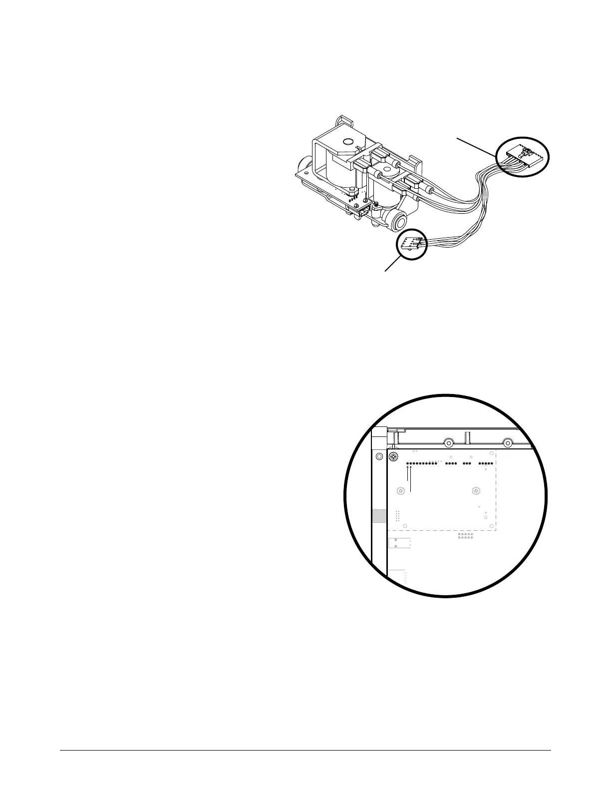
Examine the solenoid valve sensor and power PCB sensor input
1. Set the power switch to OFF (O).
2. Disconnect the solenoid valve from
J4 or J6 on the power PCB.
3. Disconnect the J1 connector from
the solenoid valve PCB.
4. Are any of the pins on the connectors
or on the solenoid valve PCB
damaged?
If yes, replace the solenoid valve.
If no, continue with the next step.
5. Reconnect the valve to J4 or J6 on
the power PCB.
6. Reconnect J1 to the solenoid valve PCB.
7. Disconnect the gas supply.
8. Set the power switch set to ON (I).
9. Do a check of the output signal from the
solenoid valve pressure sensor. If the
sensor is operating correctly, the output
signal is approximately 0.2 VDC at 0 bar
(0 psi). Measure the voltage between
pin 1 and pin 2 on J4 or J6. Is the voltage
0.18 VDC – 0.22 VDC, but you continue
to get the 2-11-n fault code?
If yes, continue with the next step. The
solenoid valve pressure sensor is
operating correctly. The DSP PCB is
not reading the pressure signal
correctly, or the power PCB is not
sending the pressure signal to the
DSP PCB.
If no, replace the solenoid valve.
R