Do System Tests to Identify Defective Components
Powermax65/85/105 SYNC Troubleshooting Guide 810430 11 7
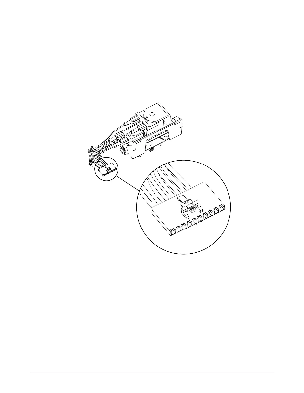
4. Measure the resistance on the solenoid valve J4 or J6 connector as follows:
The correct resistance between pin 5 and pin 6 is approximately 22 ohms (Ω) (±3 Ω).
The correct resistance between pin 7 and pin 8 is approximately 44 ohms (Ω) (±5 Ω).
Are the resistance values correct?
If yes, continue with the next step.
If no, replace the solenoid valve.
Figure 32 – Pins of solenoid valve connector