EasyManuals Logo

Hypertherm Powermax65 SYNC Troubleshooting Guide

Hypertherm Powermax65 SYNC
180 pages
To Next Page IconTo Next Page
To Previous Page IconTo Previous Page
Page #38 background imageLoading...
Page #38 background image
Prepare to Troubleshoot Internal Components
2
38 810430 Troubleshooting Guide Powermax65/85/105 SYNC
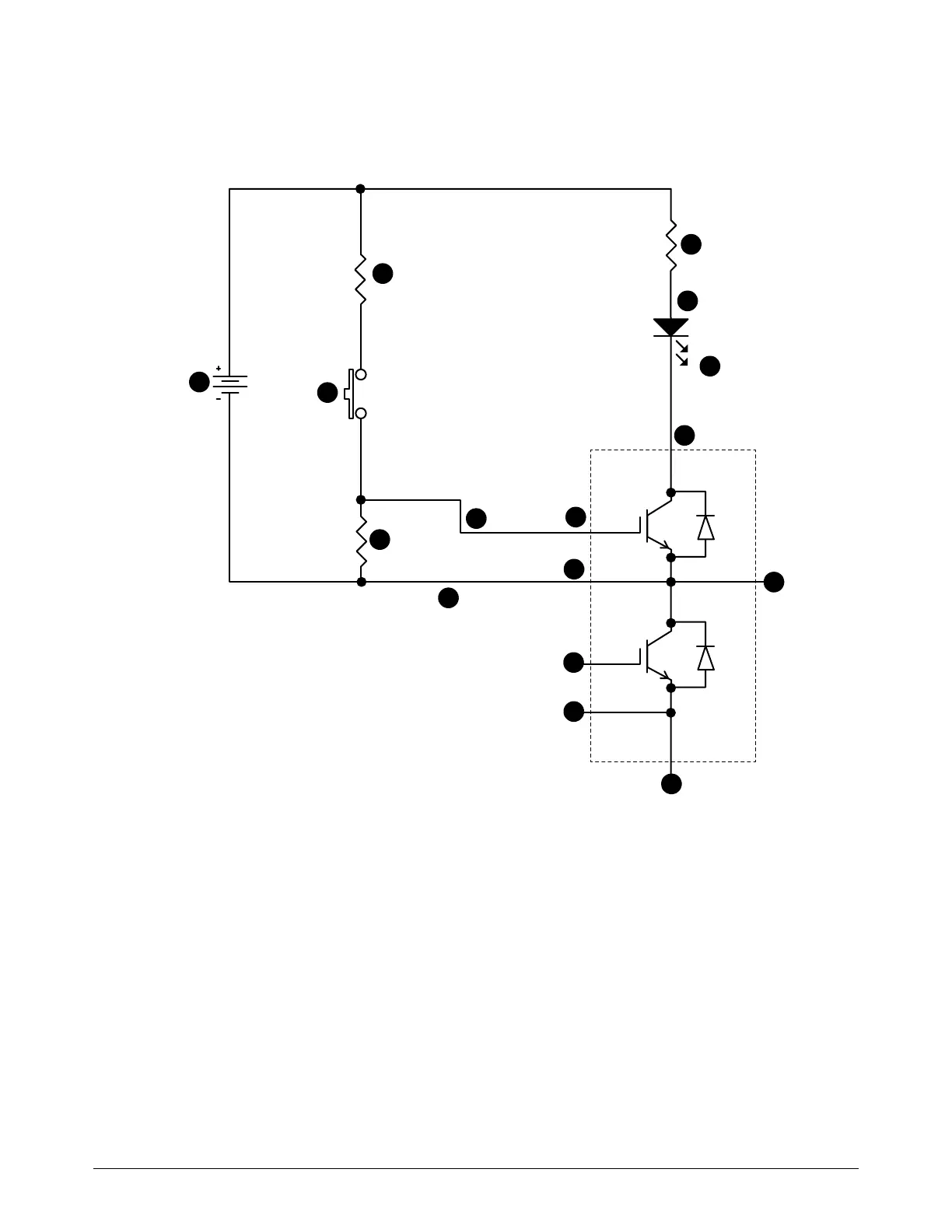
Schematic to build an IGBT tester
Figure 6 – IGBT tester schematic
7
8
9
1
2
3
4
5
6
11
13
14
15
16
12
1
0
1 Collector 1 (C1)
2 Emitter 2 (E2)
3 Collector 2, Emitter 1(C2, E1)
4 Gate 1 (G1)
5 Emitter 1 (E1)
6 Emitter 2 (E2)
7 Gate 2 (G2)
8 Red minigrabber test clip
9 D1 Red LED lamp
10 R3 2.0K
11 R4 2.0K
12 9 VDC battery
13 Normally open (N.O.) push-button switch
14 R1 3.01M
15 Black minigrabber test clip
16 Yellow minigrabber test clip

Table of Contents

Other manuals for Hypertherm Powermax65 SYNC

Questions and Answers:

Question and Answer IconNeed help?

Do you have a question about the Hypertherm Powermax65 SYNC and is the answer not in the manual?

Hypertherm Powermax65 SYNC Specifications

General IconGeneral
BrandHypertherm
ModelPowermax65 SYNC
CategoryWelding System
LanguageEnglish

Related product manuals