Do System Tests to Identify Defective Components
80 810430 Troubleshooting Guide Powermax65/85/105 SYNC
Examine the power switch and the plasma power supply
1. Make sure that the power switch on the plasma power supply is ON (I).
2. Measure the input voltage to the input diode bridge. The AC voltage between each pair of input
wires must be equal to the line voltage.
3. Is the voltage to the power switch correct, but the voltage to the input diode bridge is low?
If yes, replace the power switch.
If no, continue with the next step.
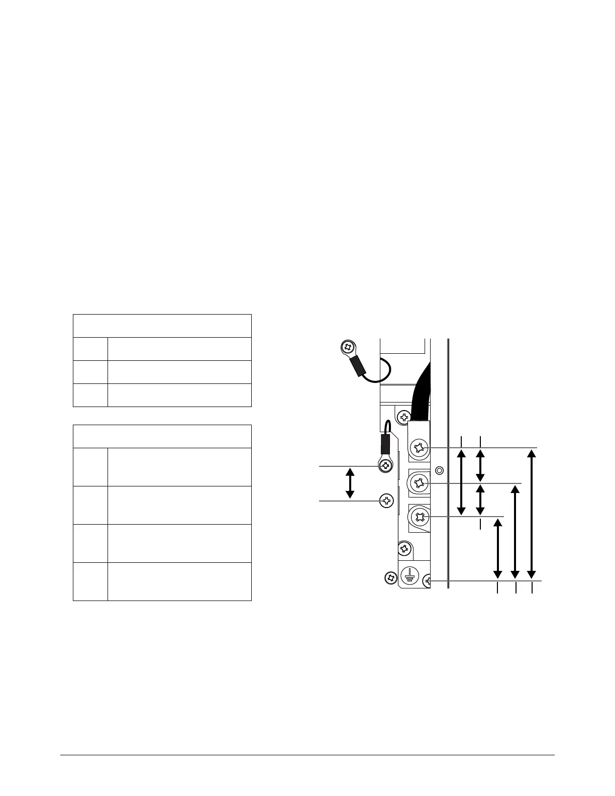
4. Measure the output voltage of the input diode bridge. Refer to Figure 10 or Figure 11.
Output VDC = Line Voltage x 1.414 VDC
All values are ±15%.
Figure 10 – Powermax65/85 SYNC
1-phase
L Black (CSA)
N White (CSA)
PE Green (CSA)
3-phase
L1
Black (CSA)
Brown (CE/CCC)
L2
White (CSA)
Black (CE/CCC)
L3
Red (CSA)
Gray (CE/CCC)
PE
Green (CSA)
Green/yellow (CE/CCC)
LV = incoming line voltage
LV X 1. 4 14
LV / 1.732
LV LV
LV