Do System Tests to Identify Defective Components
Powermax65/85/105 SYNC Troubleshooting Guide 810430 127
0-98-2 fault: torch or plasma power supply
If you see an 0-98-2 fault, do the following to identify if the cause of the fault is with the torch or with
the plasma power supply.
Do a test of the plasma power supply
1. Set the power switch on the plasma power supply to OFF (O).
2. Disconnect the SmartSYNC torch from the plasma power supply.
3. Set the power switch on the plasma power supply to ON (I).
A 0-50-0 fault code shows if the torch is disconnected when you set the
plasma power supply to ON (I).
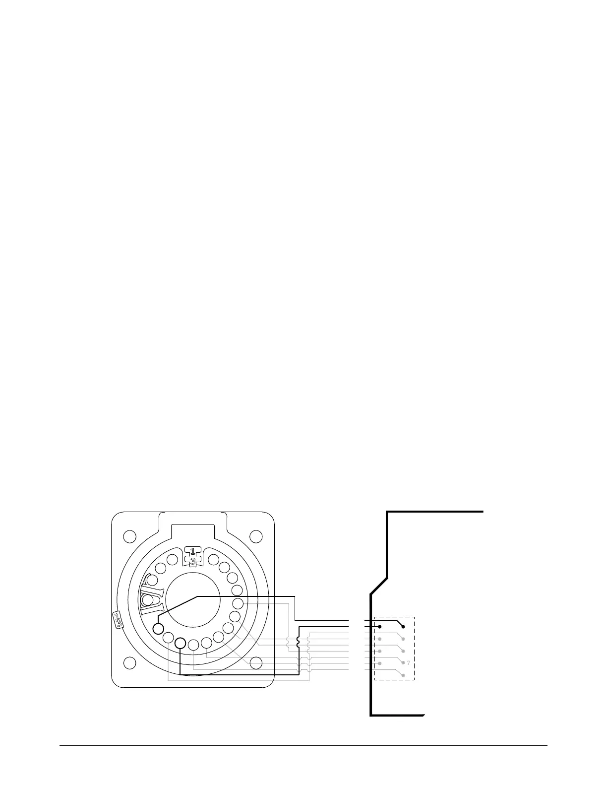
4. In the quick-disconnect receptacle on the front of the plasma power supply, measure the
voltage between pin 5 (blue wire) and pin 7 (orange wire). Refer to Figure 37. Is the voltage
approximately 18 VDC?
If yes, the problem is possibly with the torch. Continue with Do a test of the torch on
page 128.
If no, continue with the next step.
5. At the J20 connector (for Powermax65/85 SYNC) or the J17 connector (for
Powermax105 SYNC) on the power PCB, measure the voltage between pin 1 (blue wire) and
pin 2 (orange wire). Refer to Figure 37. Is the voltage approximately 18 VDC?
If yes, replace the quick-disconnect receptacle.
If no, replace the power PCB.
If communication faults continue, replace the DSP PCB.
Figure 37 – Quick-disconnect receptacle pinout
I
E
WHT
E
R
LK
BLK
BLK
1
2
3
4
5
BLU
6
VIO
7
ORG
8
BLK
9
BRN
10
GRY
11
YEL
12
WHT
13
RED
14
15
16
17