Access Service Information and Settings
Powermax65/85/105 SYNC Troubleshooting Guide 810430 147
AM RSSI L – This field shows the received signal strength indicator (RSSI) of the most recently
used amplitude modulation (AM) channel. RSSI is a measurement of how strong the radio
signal is between the transmitter and the receiver.
W/R COUNT – This field shows how many write/read occurrences have been done to the test cell.
ERROR RF – This field shows how many RF operation errors have occurred.
ERROR COM – This field shows how many torch communication errors have occurred.
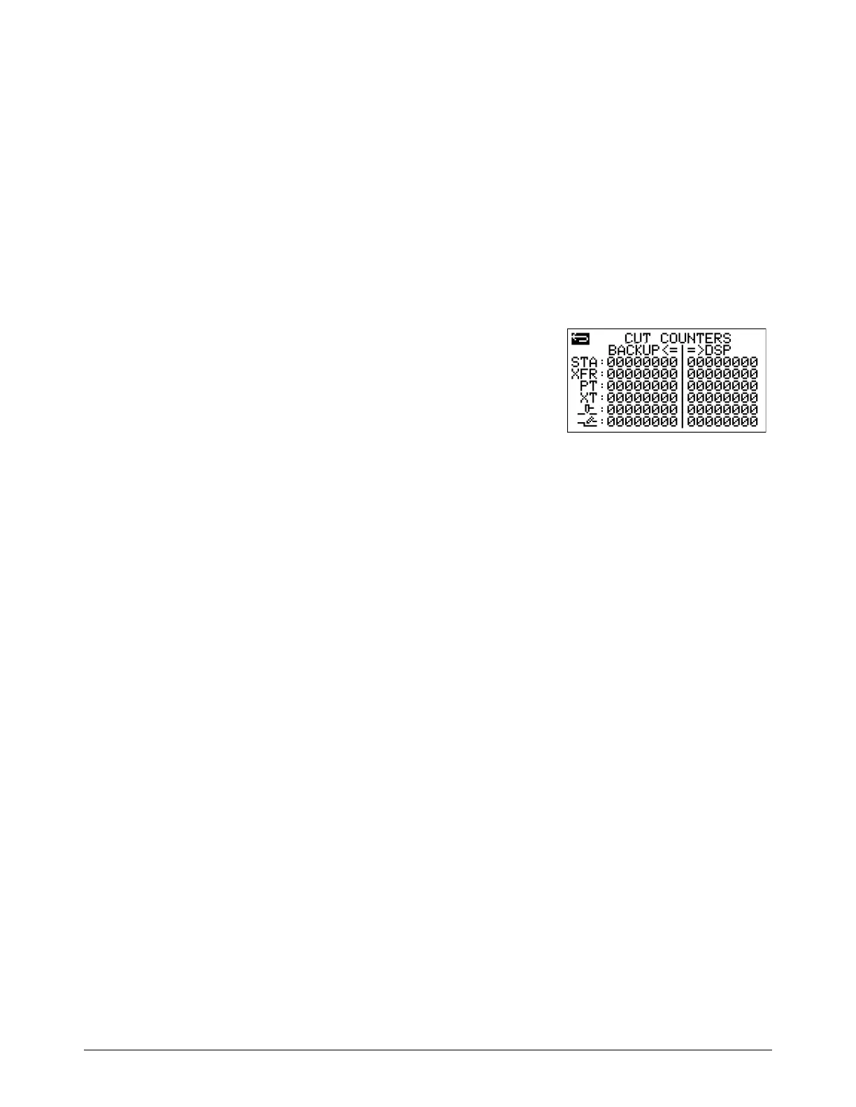
Cut counter data for backups
Go to the Cut Counters Transfer screen (CUT COUNTERS) to
do a transfer of the plasma power supply’s cut counter data
before installing a new DSP PCB.
For instructions on how to use this screen, refer to the
Powermax65/85/105 SYNC DSP PCB Replacement Field
Service Bulletin (810950).