Do System Tests to Identify Defective Components
76 810430 Troubleshooting Guide Powermax65/85/105 SYNC
System tests in this section
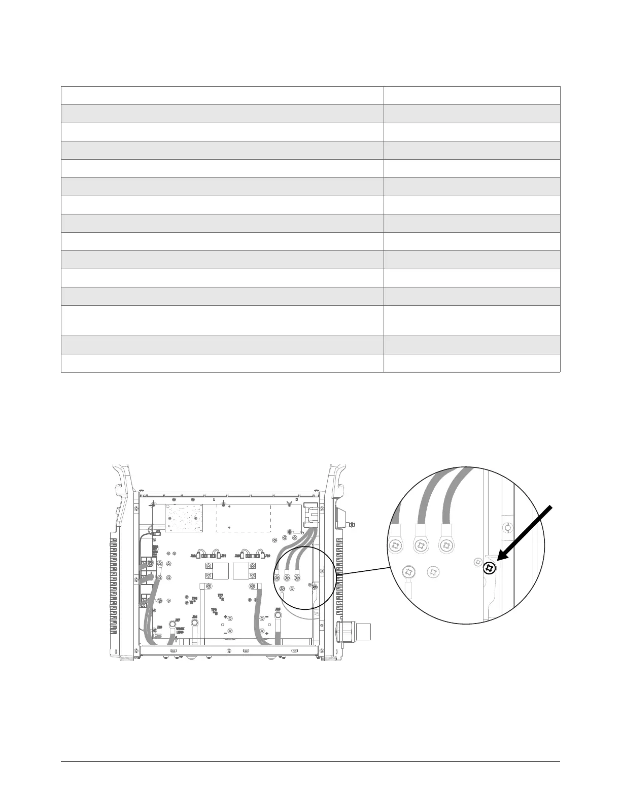
How to attach to ground
For tests where it is necessary to attach the multimeter to ground, use the ground screw on the
heatsink.
System test Associated fault codes
Test 1 – Voltage input on page 78 0-60-n
Test 2 – DC power bus on page 83 3-43-0
Test 3 – Output diodes on page 90 3-51-1, 3-52-0
Test 4 – Inverter thermal sensor and PFC temperature sensor on page 91 0-40-n, 2-10-n, 3-11-n
Test 5 – Flyback circuit (DC minor voltages) on page 94 3-00-0, 3-42-n, 3-43-n
Test 6 – Torch stuck open (TSO) or torch stuck closed (TSC) on page 98 0-30-n
Test 7 – Start signal on page 102 0-51-0, general
Test 8 – Torch cap switch on page 108 0-50-0
Test 9 – Solenoid valve electronic regulator on page 112 0-21-0, 3-20-n
Test 10 – Solenoid valve pressure sensor on page 115 0-12-0, 0-20-0, 0-22-0, 2-11-n
Test 11 – Fan on page 120 0-40-n, 3-10-n
Test 12 – Auxiliary (AUX) switch on page 123 2-01-0 or unreported interlock at
START
Test 13 – Pilot arc IG BT on page 125 General
Test 14 – Radio Frequency (RF) communication errors on page 126 0-98-1, 0-98-2