Do System Tests to Identify Defective Components
11 4 810430 Troubleshooting Guide Powermax65/85/105 SYNC
Do a test of the solenoid valve after disconnecting from the power PCB
1. Disconnect the solenoid valve from J4 or J6 on the power PCB.
2. Measure the voltage again between pin 1 and pin 7 at J4 or J6 on the power PCB. Is the voltage
approximately 48 VDC?
If yes, continue with the next step.
If no, replace the power PCB.
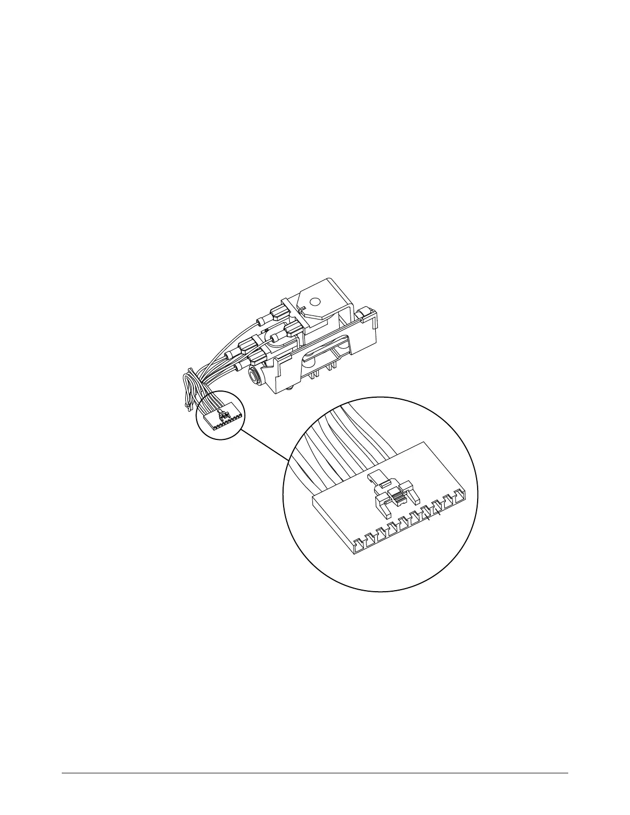
3. Do a resistance check to make sure that the solenoid valve is defective. Measure the resistance
between pin 7 and pin 8 on the solenoid valve connector. Refer to Figure 30. If the resistance is
less than 44 ohms (Ω), approximately, replace the solenoid valve.
Figure 30 – Pins on the solenoid valve connector