EasyManuals Logo

Hypertherm Powermax65 SYNC Troubleshooting Guide

Hypertherm Powermax65 SYNC
180 pages
To Next Page IconTo Next Page
To Previous Page IconTo Previous Page
Page #113 background imageLoading...
Page #113 background image
Do System Tests to Identify Defective Components
5
Powermax65/85/105 SYNC Troubleshooting Guide 810430 11 3
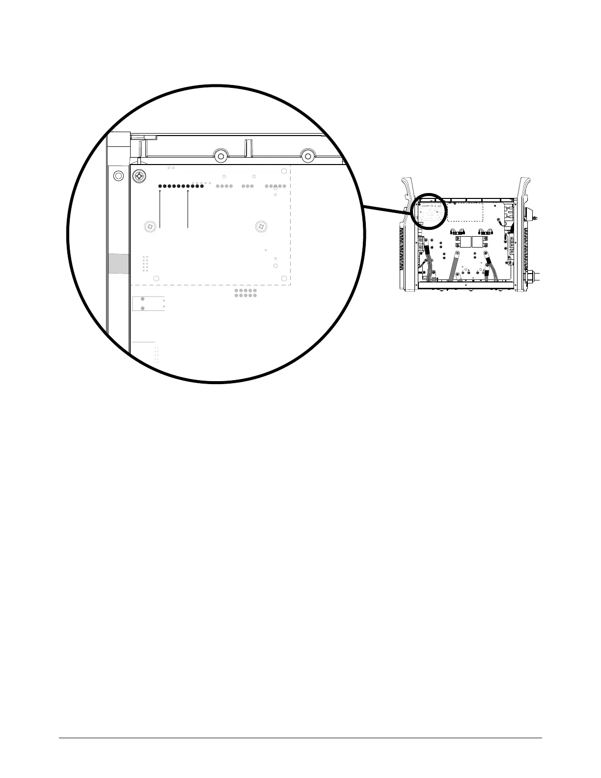
Figure 29 Solenoid valve pins on the power PCB
6. Measure the voltage between pin 1 and pin 7 at J4 or J6 on the power PCB. Refer to Figure 29.
Is the voltage approximately 48 VDC?
If yes, replace the solenoid valve.
If no, continue with Do a test of the solenoid valve after disconnecting from the power PCB
on page 114.
O
R
G
B
R
J4 / J6
1 7
RED
J32
RED
J21
ORG
J20
J12
B
R
WORK
LEAD
BLK
BLK
J13
J16J17J18J19
J26
J29
TP12
J28
TP10
TP11
W
R
B
J4 J2 J1J3
2
J3

Table of Contents

Other manuals for Hypertherm Powermax65 SYNC

Questions and Answers:

Question and Answer IconNeed help?

Do you have a question about the Hypertherm Powermax65 SYNC and is the answer not in the manual?

Hypertherm Powermax65 SYNC Specifications

General IconGeneral
BrandHypertherm
ModelPowermax65 SYNC
CategoryWelding System
LanguageEnglish

Related product manuals