Do System Tests to Identify Defective Components
Powermax65/85/105 SYNC Troubleshooting Guide 810430 77
How to get voltage measurements for internal components
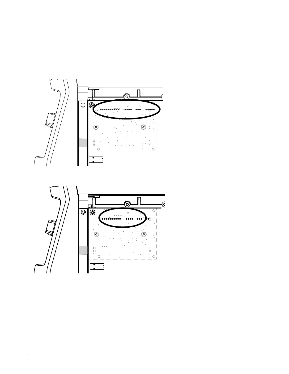
For some tests it is necessary to get access to pins on the power PCB in order to measure voltage.
The pins for the following components are behind the DSP PCB. Use extended thin meter points to
measure voltage on these pins. Refer to Get the necessary test equipment on page 16.
Figure 7 – J1, J2, J3, and J4 pins in Powermax65/85 SYNC CSA
Figure 8 – J4, J5, and J6 pins in Powermax65/85 SYNC CE/CCC
J1 = Auxiliary switch
J2 = Inverter temperature sensor
J3 = Fan
J4 = Solenoid valve electronic regulator
J4 = Inverter temperature sensor
J5 = Fan
J6 = Solenoid valve electronic regulator