How the Plasma Power Supply Operates
Powermax65/85/105 SYNC Troubleshooting Guide 810430 159
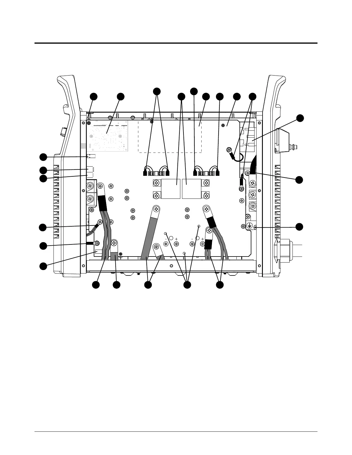
Powermax65/85 SYNC plasma power supply overviews
Figure 40 – 200 V – 600 V CSA plasma power supply
RED
J32
RED
J21
ORG
J20
J12
B
R
WORK
LEAD
BLK
BLK
J13
J16J17J18J19
J26
J29
TP12
J28
TP10
TP11
W
R
B
J4 J2 J1J3
7
8
9
1
2
3
4
5
6
11
13
14
15
16
17
18
19
12
1
0
21
20
19
22
1 J12 connector
2 J20 connector
3 J21 connector
4 Nozzle wire
5 Electrode wire
6 J32 connector
7 Output inductor wire
8 Work lead
9 Transformer wires
10 Test points
11 PFC inductor wires
12 Ground
13 AC input wires (3)
14 Power switch
15 Damper resistor wires
16 Power PCB
17 PFC temperature sensor
18 Flyback circuit
19 Gate drive connectors (3)
20 3uF capacitors
21 Digital signal processor (DSP) PCB
22 Control PCB (in front panel)