Do System Tests to Identify Defective Components
Powermax65/85/105 SYNC Troubleshooting Guide 810430 79
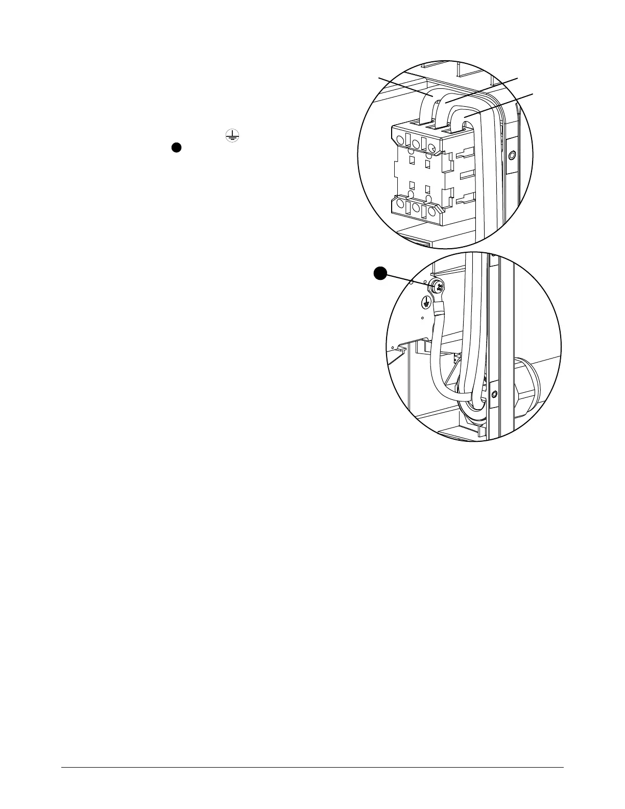
4. Measure the voltage on the input leads as
follows:
a. Measure the voltage from each input
lead to ground. The leads have the
labels L1, L2, and L3 on the power
switch. Look for the symbol on the
heatsink to identify the ground
screw.
b. Measure the line voltage across the
input leads, as follows:
L1 to L2
L2 to L3
L1 to L3
5. Is the AC voltage between each pair of
input wires equal to the line voltage of the
incoming circuit, based on the model of
the plasma power supply?
If yes, an additional check is necessary
to identify if the problem is with the
power switch or with a different
component. Continue with Examine
the power switch and the plasma
power supply.
If no, continue with the next step.
6. If the voltage across the input leads is not
correct, have a qualified service technician examine the following electrical components:
Power cord
Receptacle where the power cord connects to the power source
Circuit breakers or fuses
For example, make sure that the circuit breakers or fuses are sufficient for the plasma power
supply. For the power cord, make sure that the wires are connected to the correct locations in
the plasma power supply and in the line-disconnect box. Also make sure that the power cord
wires are fully tightened.