Prepare to Troubleshoot Internal Components
Powermax65/85/105 SYNC Troubleshooting Guide 810430 37
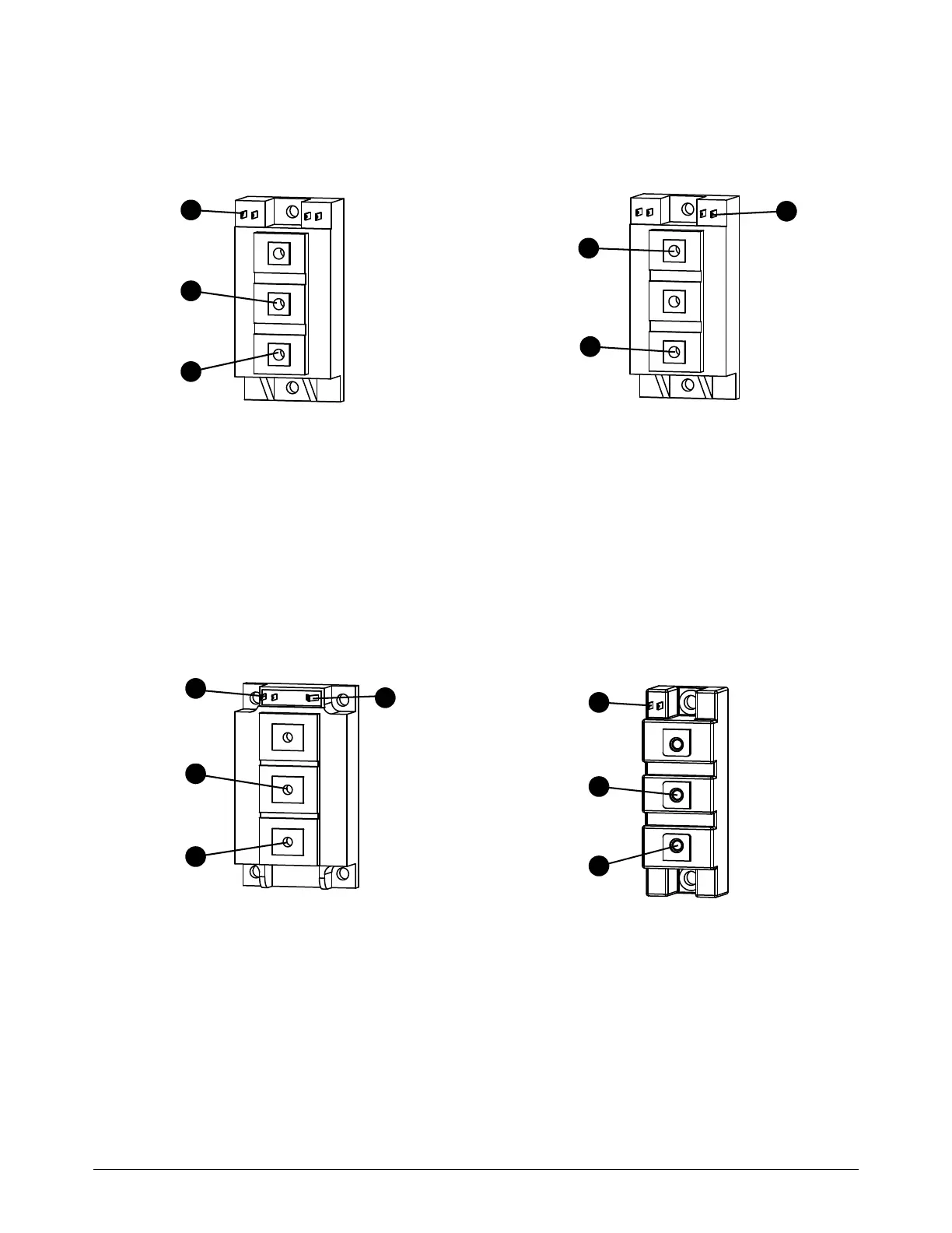
Figure 5 – Common IGBT configurations
IGBT module, Inverter test 1 IGBT module, Inverter test 2
1
2
3
4
5
6
1 Yellow lead Gate 2 (G2)
2 Black lead Emitter 2 (E2)
3 Red lead Collector 2 (C2)
4 Red lead Collector 1 (C1)
5 Black lead Emitter 1 (E1)
6 Yellow lead Gate 1 (G1)
IGBT module, PFC IGBT, Pilot arc
1
2
3
4
1
2
3
1 Yellow lead Gate (G)
2 Black lead Emitter (E)
3 Red lead Collector (C)
4 These pins are for the IGBT internal temperature
sensor. Do not use the IGBT tester here.